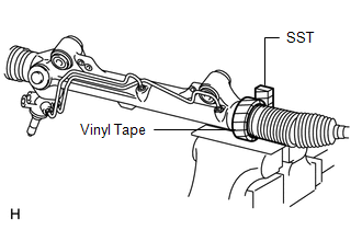
DISASSEMBLY PROCEDURE 1. FIX POWER STEERING GEAR ASSEMBLY
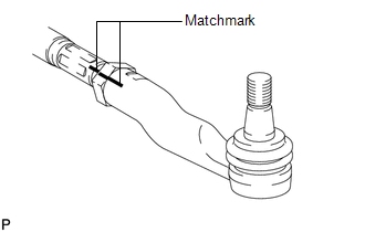
2. REMOVE TIE ROD END SUB-ASSEMBLY LH
3. REMOVE TIE ROD END SUB-ASSEMBLY RH HINT: Use the same procedures described for the LH side. 4. REMOVE STEERING RACK BOOT CLIP (a) Using pliers, remove the 2 steering rack boot clips. 5. REMOVE NO. 2 STEERING RACK BOOT CLAMP
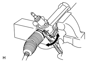
6. REMOVE NO. 2 STEERING RACK BOOT 7. REMOVE NO. 1 STEERING RACK BOOT 8. REMOVE STEERING RACK END SUB-ASSEMBLY
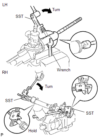
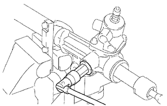
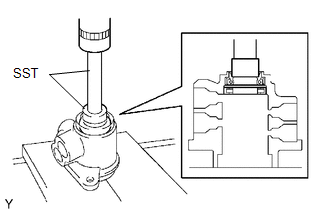
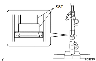
(b) Using a wrench, hold the steering rack (LH side).
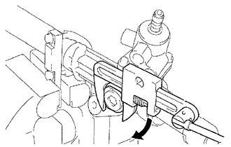
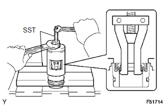
(d) Using SST, remove the steering rack end (RH side) from the power steering rack. SST: 09922-10010 NOTICE: Rotate SST in the direction shown in the illustration. (e) Remove the 2 claw washers. 9. REMOVE STEERING GEAR RACK GUIDE
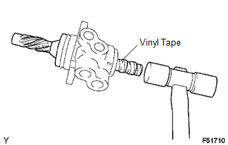
(c) Remove the spring and rack guide. 10. REMOVE POWER STEERING CONTROL VALVE
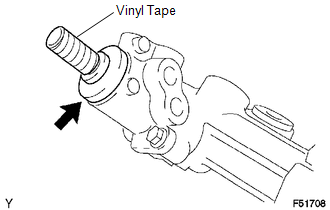
(b) Remove the dust cover from the control valve housing.
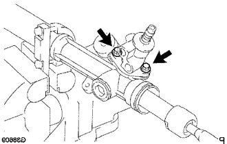
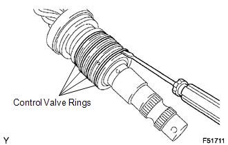
(d) Pull out the control valve from the rack housing. (e) Remove the control valve oil seal.
(g) Using a plastic-faced hammer, remove the control valve from the control valve housing.
11. REMOVE POWER STEERING CONTROL VALVE UPPER OIL SEAL
12. REMOVE CYLINDER END STOPPER
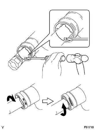
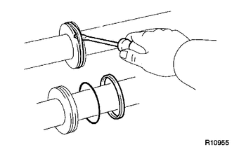
(b) Using a screwdriver and hammer, turn the cylinder end stopper counterclockwise, and remove the wire and cylinder end stopper. 13. REMOVE POWER STEERING RACK 14. REMOVE POWER STEERING RACK BUSH (a) Remove the rack bush from the power steering rack. (b) Using a screwdriver, remove the O-ring from the rack bush.
15. REMOVE POWER STEERING CYLINDER TUBE OIL SEAL
16. REMOVE RACK STEERING PISTON RING
|
Toyota Tundra Service Manual > Can Communication System: Open in One Side of Bus 4 Branch Line
DESCRIPTION When the CAN bus main lines are normal (no open, short to ground, short to +B or short between lines) and there is an ECU or sensor on the "Communication Bus Check" screen that is indicated as not communicating or whose connection status on the "Communication Bus Check" screen changes in ...