REMOVAL PROCEDURE 1. PLACE FRONT WHEELS FACING STRAIGHT AHEAD 2. REMOVE FRONT WHEELS 3. DISCONNECT NO. 2 STEERING INTERMEDIATE SHAFT SUB-ASSEMBLY
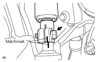
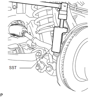
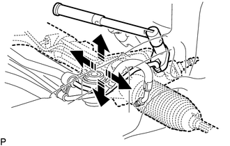
(b) Remove the bolt and disconnect the No. 2 steering intermediate shaft from the power steering gear. 4. DISCONNECT TIE ROD END SUB-ASSEMBLY LH (a) Remove the cotter pin and nut.
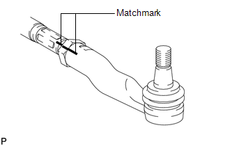
5. DISCONNECT TIE ROD END SUB-ASSEMBLY RH HINT: Use the same procedures described for the LH side. 6. REMOVE TIE ROD END SUB-ASSEMBLY LH HINT: Only remove the tie rod end sub-assembly LH. The tie rod end sub-assembly RH does not need to be removed.
(b) Remove the tie rod assembly LH and lock nut. 7. REMOVE NO. 1 ENGINE UNDER COVER Click here 8. REMOVE FRONT DIFFERENTIAL CARRIER ASSEMBLY Click here
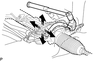
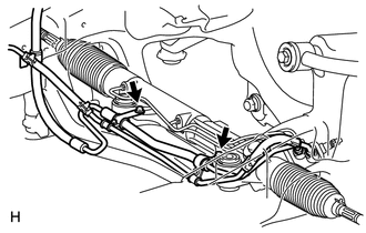
9. REMOVE POWER STEERING GEAR ASSEMBLY (a) Remove the 2 bolts, 2 nuts and power steering gear. 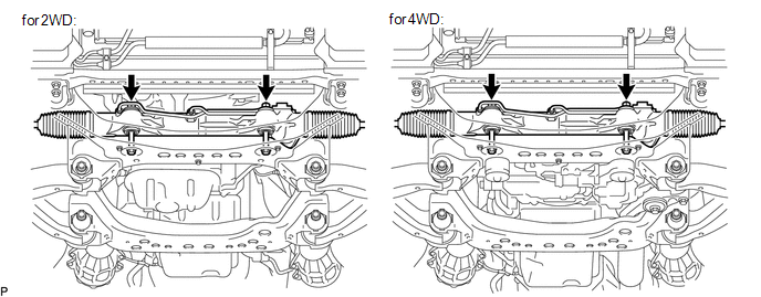
(e) Pull the power steering gear assembly out of the vehicle in the order shown in the illustration. 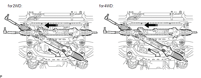
|
Toyota Tundra Service Manual > Hazard Warning Switch: Inspection
INSPECTION PROCEDURE 1. INSPECT AIR CONDITIONING CONTROL ASSEMBLY (HAZARD WARNING SWITCH) (a) Measure the resistance according to the value(s) in the table below. Standard Resistance: Tester Connection Switch Condition Specified Condition 1 (HAZ) - 5 (GND) Hazard warning switch off 10 kΩ or higher ...