INSPECTION PROCEDURE 1. INSPECT VANE PUMP SHAFT AND BUSH IN VANE PUMP FRONT HOUSING
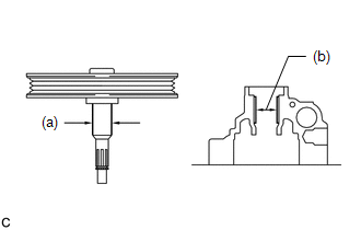
| (a) Using a micrometer, measure the diameter (a) of the vane pump shaft with vane pump pulley. |
|
(b) Using a caliper gauge, measure the inside diameter (b) of the vane pump front housing.
(c) Subtract (a) from (b) to calculate the oil clearance. Maximum clearance:
0.07 mm (0.00276 in.) If it is more than the maximum, replace the vane pump shaft with vane pump pulley.
2. INSPECT VANE PUMP ROTOR AND VANE PUMP PLATE (a) Inspect the vane pump rotor groove and vane pump plate clearance.
| (1) Using a feeler gauge, measure the clearance between the side face of the vane pump rotor groove and the vane pump plates.
Maximum clearance: 0.03 mm (0.00118 in.) Text in Illustration |
|
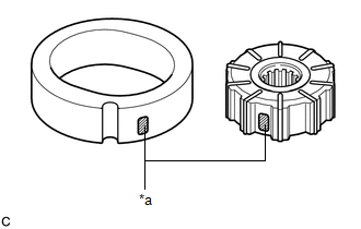
| (2) If the clearance is more than the maximum, replace the vane pump plates, vane pump rotor and vane pump cam ring. Text in Illustration
NOTICE:
- Check the marks on the vane pump rotor and vane pump cam ring.
- Refer to the following table to select an appropriate combination of vane pump rotor, vane pump cam ring and vane pump plates.
Combination of vane pump rotor, vane pump cam ring and vane pump plates: |
Vane Pump Rotor Mark (Part No.) |
Vane Pump Cam Ring Mark (Part No.) |
Vane Pump Plate Part No. |
Vane Pump Plate Length | |
0 (44313-60010) |
0 (44325-0C160) |
44345-0C010 | 18.505 to 18.503 mm
(0.72854 to 0.72846 in.) | |
1 (44313-60020) |
1 (44325-0C170) |
44345-0C020 | 18.502 to 18.501 mm
(0.72842 to 0.72838 in.) | |
2 (44313-60030) |
2 (44325-0C180) |
44345-0C030 | 18.500 to 18.499 mm
(0.72835 to 0.72831 in.) | |
3 (44313-60040) |
3 (44325-0C190) |
44345-0C040 | 18.498 to 18.497 mm
(0.72827 to 0.72823 in.) | |
4 (44313-60050) |
4 (44325-0C200) |
44345-0C050 | 18.496 to 18.495 mm
(0.72819 to 0.72815 in.) | |
|
(b) Inspect the vane pump plate.
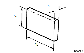
| (1) Using a micrometer, measure the thickness of the vane pump plates.
Standard thickness: 1.405 to 1.411 mm (0.05531 to 0.05555 in.) Text in Illustration |
*a | Height | |
*b | Length | |
*c | Thickness | |
|
(2) If the thickness is not within the specified range, replace the vane pump plates.
3. INSPECT FLOW CONTROL VALVE ASSEMBLY (a) Check the flow control valve for leakage.
| (1)
Close one of the holes and apply compressed air of 392 - 490 kPa (4 - 5
kgf*cm2, 57 - 71 psi) into the opposite side hole, and confirm that air
does not come out from the end holes. Text in Illustration |
|
| (2) If there is leakage, replace the flow control valve. Text in Illustration
NOTICE:
- Check the mark on the vane pump front housing and replace the flow
control valve with one having the same mark as that of the vane pump
front housing.
- Refer to the following table to select an appropriate combination of vane pump front housing and flow control valve.
Combination of vane pump front housing and flow control valve: |
Vane Pump Front Housing Mark |
Flow Control Valve Mark |
Flow Control Valve Part No. | |
A | A |
44330-0C010 | |
B | B |
44330-0C020 | |
C | C |
44330-0C030 | |
D | D |
44330-0C040 | |
E | E |
44330-0C050 | |
F | F |
44330-0C060 | | |
(b) Check the flow control valve and vane pump front housing. (1) Coat the flow control valve with power steering fluid.
| (2)
Insert the flow control valve into the flow control valve installation
hole of the vane pump front housing, and check that the flow control
valve enters smoothly under its own weight. | |
(3) If the flow control valve does not enter the housing smoothly, replace the flow control valve.
4. INSPECT FLOW CONTROL VALVE COMPRESSION SPRING
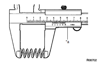
| (a) Using vernier calipers, measure the free length of the flow control valve compression spring.
Minimum free length: 29.2 mm (1.15 in.) Text in Illustration
If it is not within the specification, replace the flow control valve compression spring. |
|
5. INSPECT PRESSURE PORT UNION SUB-ASSEMBLY (a)
If the union seat in the pressure port union is severely damaged, it
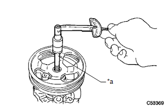
may cause fluid leakage. In that case, replace the pressure port union. 6. INSPECT TOTAL PRELOAD
(a) Check that the pump rotates smoothly without abnormal noise.
| (b) Temporarily install the service bolt. Recommended service bolt: |
Thread diameter | Thread pitch |
Bolt length | |
10 mm (0.394 in.) |
1.25 mm (0.0492 in.) |
50 mm (1.97 in.) | |
|
(c) Using a torque wrench, measure the pumps rotating torque. Standard rotating torque:
0.3 N*m (3 kgf*cm, 2 in.*lbf) or less If the rotating torque is not as specified, check the vane pump housing oil seal. |