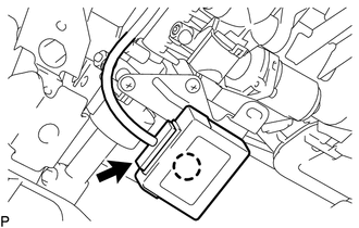
INSTALLATION PROCEDURE 1. INSTALL MULTIPLEX TILT AND TELESCOPIC ECU
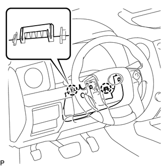
(b) Connect the ECU connector. 2. INSTALL NO. 3 AIR DUCT SUB-ASSEMBLY Click here 3. INSTALL LOWER NO. 1 INSTRUMENT PANEL AIRBAG ASSEMBLY Click here 4. INSTALL LOWER INSTRUMENT PANEL FINISH PANEL SUB-ASSEMBLY LH Click here 5. INSTALL COWL SIDE TRIM BOARD LH Click here 6. INSTALL FRONT DOOR SCUFF PLATE LH Click here 7. INSTALL INSTRUMENT SIDE PANEL LH Click here 8. INSTALL LOWER STEERING COLUMN COVER
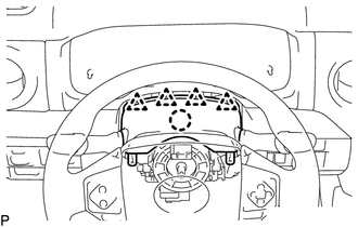
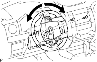
9. INSTALL UPPER STEERING COLUMN COVER
(b) Attach the 4 clips to install the upper steering cover onto the instrument panel cluster finish panel.
10. CONNECT CABLE FROM NEGATIVE BATTERY TERMINAL Torque: 5.4 N·m {55 kgf·cm, 48 in·lbf} NOTICE: When disconnecting the cable. some systems need to be initialized after the cable is reconnected (See page
11. CHECK SRS WARNING LIGHT (See page
|
Toyota Tundra Service Manual > Engine Immobiliser System (w/o Smart Key System): Registration
REGISTRATION PROCEDURE 1. NOTICES WHEN REGISTRATION PROCEDURE NOTICE: Make sure to check the items listed below before proceeding with troubleshooting. Do not perform "Immobiliser Code Reset" (all key ID erasure) until all of the malfunctions and symptoms have been confirmed and resolved. ...