COMPONENTS ILLUSTRATION 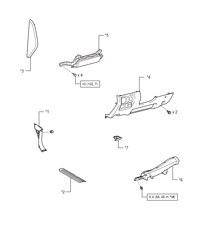
ILLUSTRATION 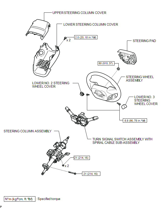 ILLUSTRATION 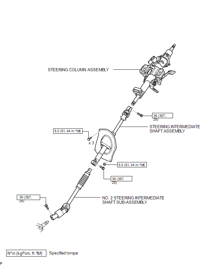 ILLUSTRATION 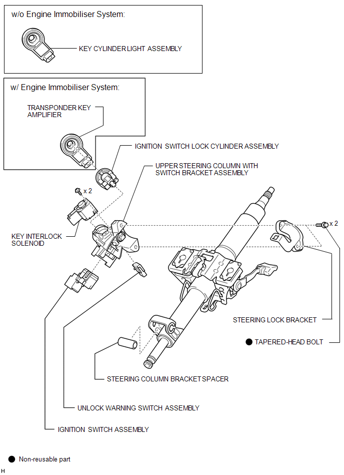 |
Toyota Tundra Service Manual > Front Passenger Airbag Assembly: Disposal
DISPOSAL CAUTION / NOTICE / HINT CAUTION: Before performing pre-disposal deployment of any SRS component, review and closely follow all applicable environmental and hazardous material regulations. Pre-disposal deployment may be considered hazardous material treatment. PROCEDURE 1. PRECAUTION CAUTION ...


