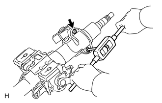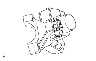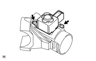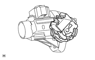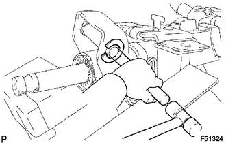
DISASSEMBLY CAUTION / NOTICE / HINT NOTICE: When using a vise, do not overtighten it. PROCEDURE 1. REMOVE TRANSPONDER KEY AMPLIFIER (w/ Engine Immobiliser System) 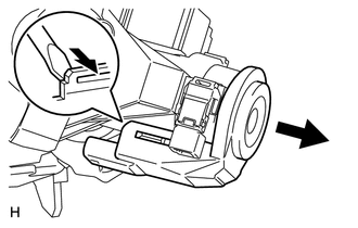 (a) Using a screwdriver, widen the claws attached to the upper bracket by approximately 1.0 mm (0.0394 in.). (b) Pull out the transponder key amplifier with the claws open. NOTICE: Using excessive force may damage the case. 2. REMOVE KEY CYLINDER LIGHT ASSEMBLY (w/o Engine Immobiliser System) (a) Using a screwdriver, widen the claws attached to the upper bracket by approximately 1.0 mm (0.0394 in.). (b) Pull out the key cylinder light with the claws open. NOTICE: Using excessive force may damage the case. 3. REMOVE UPPER STEERING COLUMN WITH SWITCH BRACKET ASSEMBLY (a) Secure the steering column in a vise. (b) Using a center punch, mark the center of the 2 tapered-head bolts. (c) Using a 3 to 4 mm (0.119 to 0.159 in.) drill, drill a hole in the 2 tapered-head bolts.
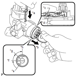
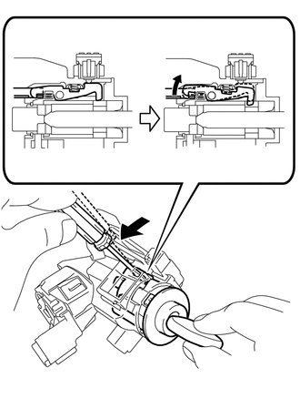
4. REMOVE IGNITION SWITCH LOCK CYLINDER ASSEMBLY (a) Turn the ignition switch lock cylinder to the ACC position.
5. REMOVE UNLOCK WARNING SWITCH ASSEMBLY
6. REMOVE KEY INTERLOCK SOLENOID
7. REMOVE IGNITION SWITCH ASSEMBLY
8. REMOVE STEERING COLUMN BRACKET SPACER
(b) Remove the No. 1 tilt steering support collar from the lower steering column tube. |
Toyota Tundra Service Manual > Engine Immobiliser System (w/o Smart Key System): Terminals Of Ecu
TERMINALS OF ECU CHECK TRANSPONDER KEY ECU ASSEMBLY (a) Disconnect the J26 transponder key ECU assembly connector. (b) Measure the resistance and voltage according to the value(s) in the table below. HINT: Measure the values on the wire harness side with the connector disconnected. Tester Connection ...