COMPONENTS ILLUSTRATION 
ILLUSTRATION  ILLUSTRATION 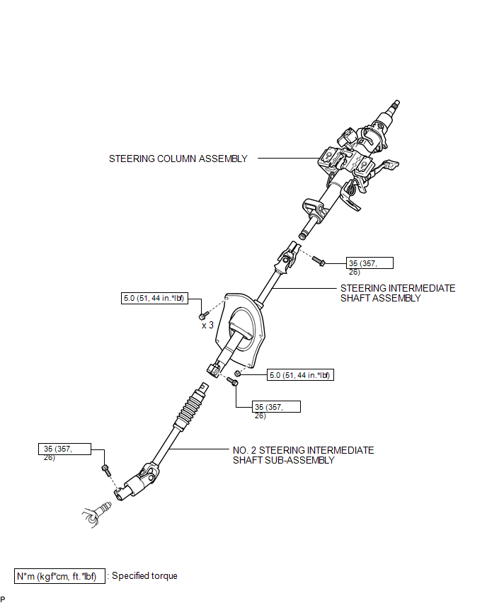 ILLUSTRATION 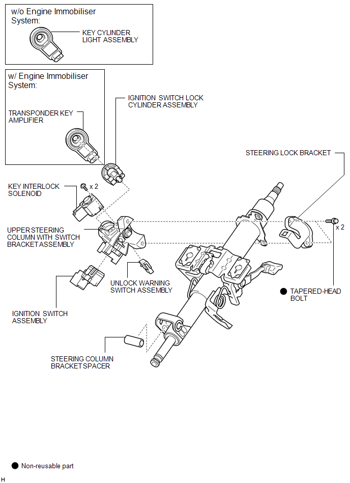 |
Toyota Tundra Service Manual > Dynamic Radar Cruise Control System: System Diagram
SYSTEM DIAGRAM Communication Table Sender Receiver Signal Line ECM Millimeter Wave Radar Sensor Assembly Cruise control operation signal Accelerator pedal idle position signal Accel override operation signal Cruise control speed status signal Approach warning signal Brake signal Cruise control main ...


