Toyota Tundra Service Manual: Reassembly

REASSEMBLY

PROCEDURE

1. INSTALL STEERING COLUMN BRACKET SPACER

(a) Fix the steering column in a vise between aluminum plates or a cloth. Then install the steering column bracket spacer to the steering column.

Text in Illustration

*a

15°

NOTICE:

  • Install the steering column bracket spacer so that it is facing in the direction shown in the illustration.
  • When using a vise, do not overtighten it.

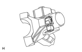
2. INSTALL IGNITION SWITCH ASSEMBLY

(a) Attach the 2 claws to install the ignition switch to the bracket switch.

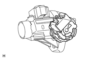
3. INSTALL KEY INTERLOCK SOLENOID

(a) Install the key interlock solenoid to the bracket switch with the 2 screws.

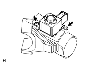
4. INSTALL UNLOCK WARNING SWITCH ASSEMBLY

(a) Attach the 2 claws to install the unlock warning switch to the switch bracket.

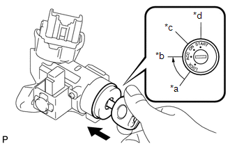
5. INSTALL IGNITION SWITCH LOCK CYLINDER ASSEMBLY

(a) Check that the ignition switch lock cylinder is in the ACC position.

(b) Install the ignition switch lock assembly to the switch bracket.

Text in Illustration

*a

LOCK

*b

ACC

*c

ON

*d

START

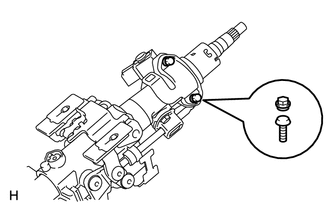
(c) Check that the ignition switch lock cylinder is securely installed.

6. INSPECT STEERING LOCK OPERATION

7. INSTALL UPPER STEERING COLUMN WITH SWITCH BRACKET ASSEMBLY

(a) Temporarily install the steering column upper with switch bracket and the steering lock bracket with 2 new tapered-head bolts.

(b) Tighten the 2 tapered-head bolts until the bolt heads break off.

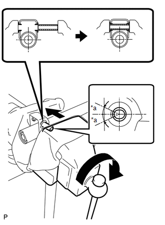
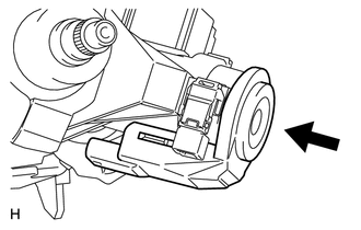
8. INSTALL TRANSPONDER KEY COIL

(a) Align the transponder key coil with the installation position of the switch bracket with the amplifier inclined.

(b) Push the transponder key coil upward and install it to the switch bracket.

NOTICE:

Do not push the amplifier up with excessive force.

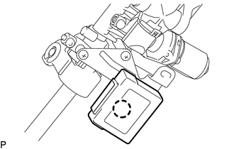
9. INSTALL MULTIPLEX TILT AND TELESCOPIC ECU

(a) Attach the claw to Install the multiplex tilt and telescopic ECU.

    On-vehicle Inspection

    Removal

    See More:

    Toyota Tundra Service Manual > Instrument Panel Speaker(for Crewmax): Removal
    REMOVAL PROCEDURE 1. REMOVE FRONT PILLAR GARNISH LH 2. REMOVE FRONT PILLAR GARNISH RH 3. REMOVE NO. 1 INSTRUMENT PANEL SPEAKER PANEL SUB-ASSEMBLY Text in Illustration *1 Protective Tape (a) Apply protective tape as shown in the illustration. (b) Using moulding remover B, detach the 3 clips, 3 claws ...

    Toyota Tundra Owners Manual

    Toyota Tundra Service Manual

    © 2024 Copyright www.ttundra.com
    0.0102