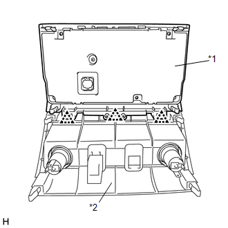
Components COMPONENTS ILLUSTRATION 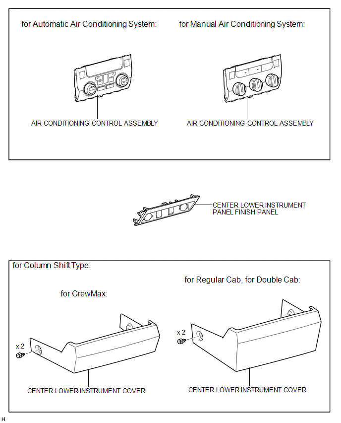
Installation INSTALLATION PROCEDURE 1. INSTALL AIR CONDITIONING CONTROL ASSEMBLY
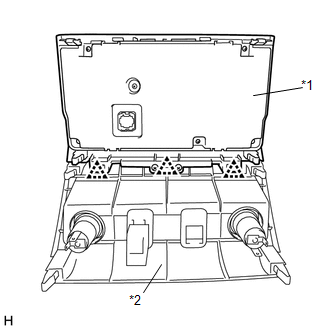
(b) Put protective tape around the air conditioning control assembly. 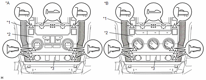 Text in Illustration Text in Illustration
(c) Connect each connector. (d) Attach the 8 clips, 2 claws and guide to install the air conditioning control assembly together with the center lower instrument panel finish panel. 2. INSTALL FRONT CONSOLE BOX (for Floor Shift Type) (See page 3. INSTALL CENTER LOWER INSTRUMENT COVER (for Column Shift Type)
Removal REMOVAL PROCEDURE 1. REMOVE FRONT CONSOLE BOX (for Floor Shift Type) (See page 2. REMOVE CENTER LOWER INSTRUMENT COVER (for Column Shift Type)
3. REMOVE AIR CONDITIONING CONTROL ASSEMBLY (a) Put protective tape around the air conditioning control assembly. 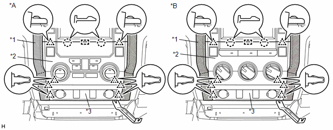 Text in Illustration Text in Illustration
(b) Using moulding remover B, detach the 8 clips, 2 claws and guide. (c) Disconnect each connector and remove the air conditioning control assembly together with the center lower instrument panel finish panel.
|
Toyota Tundra Service Manual > Hazard Warning Switch: Inspection
INSPECTION PROCEDURE 1. INSPECT AIR CONDITIONING CONTROL ASSEMBLY (HAZARD WARNING SWITCH) (a) Measure the resistance according to the value(s) in the table below. Standard Resistance: Tester Connection Switch Condition Specified Condition 1 (HAZ) - 5 (GND) Hazard warning switch off 10 kΩ or higher ...

 )
) )
)