DESCRIPTION The solar sensor, which is installed on the upper side of the instrument panel, detects sunlight and controls the air conditioning in AUTO mode. The output current from the solar sensor varies according to the amount of sunlight. When the sunlight increases, the output current increases. As the sunlight decreases, the output current decreases. The air conditioning amplifier detects output current from the solar sensor. 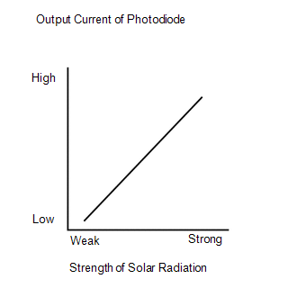
WIRING DIAGRAM 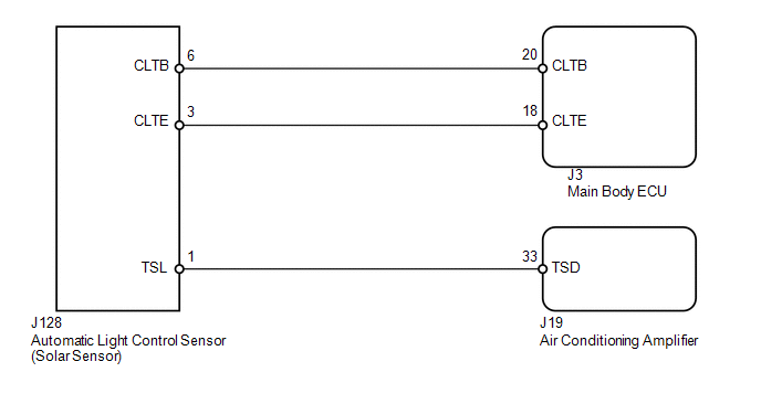
CAUTION / NOTICE / HINT HINT: If DTC B1244 is output at the same time, troubleshoot DTC B1244 first (see page
PROCEDURE
(a) Use the Data List to check if the driver side solar sensor is functioning properly. Air Conditioner
OK: The display is as specified in the normal condition. Result
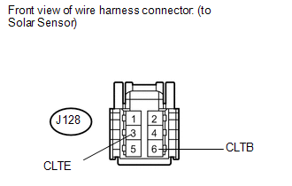
(a) Disconnect the J128 solar sensor connector. (b) Measure the resistance according to the value(s) in the table below. Standard resistance:
(c) Measure the voltage according to the value(s) in the table below. Standard voltage:
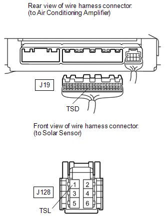
(a) Disconnect the J19 air conditioning amplifier connector. (b) Disconnect the J128 solar sensor connector. (c) Measure the resistance according to the value(s) in the table below. Standard resistance:
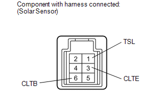
(a) Remove the solar sensor with its connector still connected (see page
(b) Apply battery voltage between terminals 6 (CLTB) and 3 (CLTE) of the solar sensor. (c) Measure the voltage according to the value(s) in the table below. Standard voltage:
HINT:
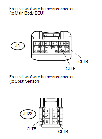
(a) Disconnect the J3 ECU connector. (b) Disconnect the J128 solar sensor connector. (c) Measure the resistance according to the value(s) in the table below. Standard resistance:
|
Toyota Tundra Service Manual > Emission Control System: On-vehicle Inspection
ON-VEHICLE INSPECTION PROCEDURE 1. INSPECT FUEL CUT-OFF OPERATION (a) Start and warm up the engine. (b) Open the throttle valve and keep the engine speed at 3000 rpm. (c) Use a sound scope to check for injector operating noise. (d) Check that when the accelerator pedal is released, injector operatio ...


