Toyota Tundra Service Manual: Blower Motor Circuit

DESCRIPTION

The blower motor is operated by signals from the air conditioning amplifier. Blower motor speed signals are transmitted by changes in the duty ratio.

Duty Ratio:

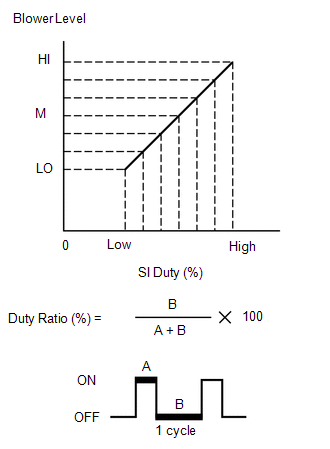
The duty ratio is the ratio of the blower motor OFF time (B) to the total of the blower motor ON and OFF time (A + B).

The blower motor controller controls the blower motor speed.

WIRING DIAGRAM
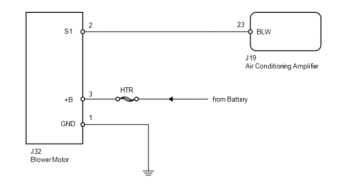
PROCEDURE

1.

PERFORM ACTIVE TEST USING TECHSTREAM (BLOWER MOTOR)

(a) Select the Active Test, using the Techstream to generate a control command, and then check that the blower motor operates.

Air Conditioner

Tester Display

Test Part

Control Range

Diagnostic Note

Blower Motor

Blower motor

Min.: 0, Max.: 31

-

Result

Result

Proceed to

NG (blower motor does not operate)

A

NG (blower motor operates but does not change speed)

B

OK

C

B

GO TO STEP 5

C

PROCEED TO NEXT CIRCUIT INSPECTION SHOWN IN PROBLEM SYMPTOMS TABLE

A

2.

INSPECT FUSE (HTR)

(a) Remove the HTR H-fuse from the engine room relay block.

(b) Measure the resistance according to the value(s) in the table below.

Standard resistance:

Tester Connection

Condition

Specified Condition

HTR H-fuse

Always

Below 1 Ω

NG

REPLACE FUSE

OK

3.

CHECK HARNESS AND CONNECTOR (BLOWER MOTOR - BATTERY AND BODY GROUND)

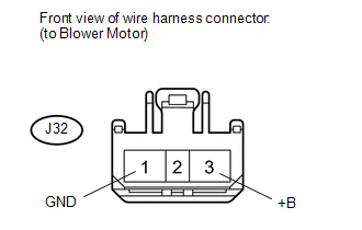
(a) Disconnect the J32 blower motor connector.

(b) Measure the resistance and voltage according to the value(s) in the table below.

Standard resistance:

Tester Connection

Condition

Specified Condition

J32-1 (GND) - Body ground

Always

Below 1 Ω

Standard voltage:

Tester Connection

Condition

Specified Condition

J32-3 (+B) - Body ground

Always

11 to 14 V

NG

REPAIR OR REPLACE HARNESS OR CONNECTOR

OK

4.

CHECK HARNESS AND CONNECTOR (AIR CONDITIONING AMPLIFIER - BLOWER MOTOR)

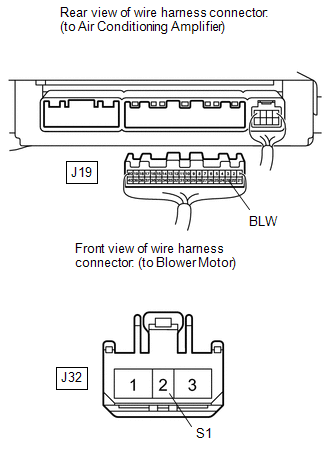
(a) Disconnect the J19 air conditioning amplifier connector.

(b) Disconnect the J32 blower motor connector.

(c) Measure the resistance according to the value(s) in the table below.

Standard resistance:

Tester Connection

Condition

Specified Condition

J19-23 (BLW) - J32-2 (S1)

Always

Below 1 Ω

J19-23 (BLW) or J32-2 (S1) - Body ground

Always

10 kΩ or higher

NG

REPAIR OR REPLACE HARNESS OR CONNECTOR

OK

5.

CHECK BLOWER MOTOR (S1 VOLTAGE)

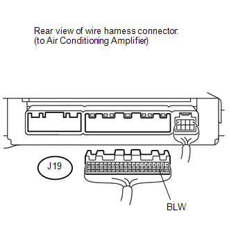
(a) Disconnect the J19 air conditioning amplifier connector.

(b) Reconnect the J32 blower motor connector.

(c) Measure the voltage according to the value(s) in the table below.

Standard voltage:

Tester Connection

Switch Condition

Specified Condition

J19-23 (BLW) - Body ground

Ignition switch ON

4.5 to 5.5 V

NG

REPLACE BLOWER MOTOR

OK

6.

CHECK AIR CONDITIONING AMPLIFIER (BLW VOLTAGE)

(a) Remove the air conditioning amplifier with its connectors still connected
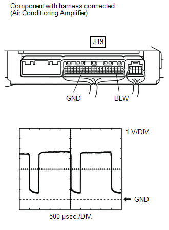
 (see page ).

(b) Turn the ignition switch ON.

(c) Turn the blower switch LO.

(d) Using an oscilloscope, check the waveform.

Standard:

Tester Connection

Tool Setting

Switch Condition

Specified Condition

J19-23 (BLW) - J19-14 (GND)

1 V/DIV., 500 μsec./DIV.

Ignition switch ON

Blower switch LO

Pulse generation

HINT:

Waveform varies with the blower level.

OK

PROCEED TO NEXT CIRCUIT INSPECTION SHOWN IN PROBLEM SYMPTOMS TABLE

NG

REPLACE AIR CONDITIONING AMPLIFIER

    Multiplex Communication Circuit (B1499/99)

    Check Mode Procedure

    See More:

    Toyota Tundra Service Manual > Key Reminder Warning System: Terminals Of Ecu
    TERMINALS OF ECU 1. CHECK DRIVER SIDE JUNCTION BLOCK ASSEMBLY, MAIN BODY ECU (MULTIPLEX NETWORK BODY ECU) (a) Remove the main body ECU (multiplex network body ECU) from the driver side junction block assembly. Click here (b) Connect the driver side junction block assembly connectors. (c) Measure the ...

    Toyota Tundra Owners Manual

    Toyota Tundra Service Manual

    © 2024 Copyright www.ttundra.com
    0.0094