DESCRIPTION This circuit provides power to operate the air conditioning amplifier. WIRING DIAGRAM 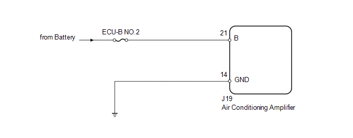
PROCEDURE
(a) Remove the ECU-B NO.2 fuse from the driver side junction block. (b) Measure the resistance according to the value(s) in the table below. Standard resistance:
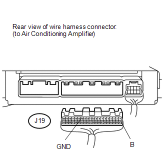
(a) Disconnect the J19 air conditioning amplifier connector. (b) Measure the resistance and voltage according to the value(s) in the table below. Standard resistance:
Standard voltage:
|
Toyota Tundra Service Manual > Front Axle Hub: On-vehicle Inspection
ON-VEHICLE INSPECTION PROCEDURE 1. REMOVE FRONT WHEEL 2. DISCONNECT FRONT DISC BRAKE CALIPER ASSEMBLY LH 3. REMOVE FRONT DISC 4. REMOVE FRONT AXLE HUB GREASE CAP LH (for 4WD) 5. INSPECT FRONT AXLE HUB BEARING LOOSENESS (a) Using a dial indicator, measure the looseness near the center of the axle hub ...


