DESCRIPTION When the ignition switch is turned ON, positive (+) battery voltage is applied to the air conditioning amplifier. WIRING DIAGRAM 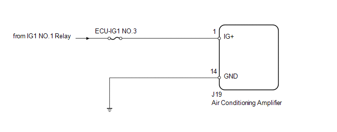
PROCEDURE
(a) Remove the ECU-IG1 NO.3 fuse from the driver side junction block. (b) Measure the resistance according to the value(s) in the table below. Standard resistance:
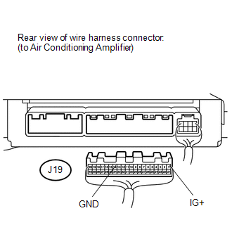
(a) Disconnect the J19 air conditioning amplifier connector. (b) Measure the resistance and voltage according to the value(s) in the table below. Standard resistance:
Standard voltage:
|
Toyota Tundra Service Manual > Sfi System: Parts Location
PARTS LOCATION ILLUSTRATION ILLUSTRATION ILLUSTRATION ILLUSTRATION ILLUSTRATION ...


