SYSTEM DESCRIPTION
1. GENERAL
(a) The air conditioning system has the following controls:
|
Control
|
Outline
|
|
Outlet Air Temperature Control
|
Based on the temperature set by the temperature control switch, the neural
network control calculates the outlet air temperature based on the input
signals from various sensors.
The temperature setting for the driver and front passenger are controlled
independently in order to provide different vehicle interior temperatures
for the right and left side of the cabin. As a result, the air conditioning
system accommodates the occupants' preferences.
|
|
Blower Control
|
Controls the blower motor in accordance with the airflow volume that
has been calculated by the neural network control based on the input signals
from various sensors.
|
|
Air Outlet Control
|
Automatically switches the air outlets in accordance with the outlet
mode that has been calculated by the neural network control based on the
input signals from various sensors.
In accordance with the engine coolant temperature, outside air temperature,
amount of sunlight, required blower, outlet temperature, and vehicle speed
conditions, this control automatically switches the blower outlet to the
FOOT / DEF mode to prevent the windows from becoming fogged when the outside
air temperature is low.
|
|
Air Inlet Control
|
Automatically controls the air inlet control damper to achieve the calculated
required outlet air temperature.
Drives the servo motor (for air inlet) according to the operation of
the air inlet control switch and moves the dampers to the FRESH or RECIRC
position.
|
|
Compressor Control
|
Through the calculation of the target evaporator temperature based on
various sensor signals, the air conditioning amplifier optimally controls
the discharge capacity by regulating the opening extent of the air conditioning
compressor solenoid valve.
The air conditioning amplifier compares the pulley speed signals, which
are transmitted by the lock sensor located on the air conditioning compressor,
with the engine speed signals, which are transmitted by the ECM (crankshaft
position sensor). When the air conditioning amplifier determines that the
pulley is locked, it turns off the magnetic clutch.
|
|
Neural Network Control
|
This control is capable of effecting complex control by artificially
simulating the information processing method of the nervous system of living
organisms in order to establish a complex input / output relationship that
is similar to a human brain.
|
|
Self-Diagnosis
|
A DTC (Diagnostic Trouble Code) is stored in the memory when the air
conditioning amplifier detects a problem with the air conditioning system.
|
2. MODE POSITION AND DAMPER OPERATION (for Double Cab)
(a) Mode Position and Damper Operation
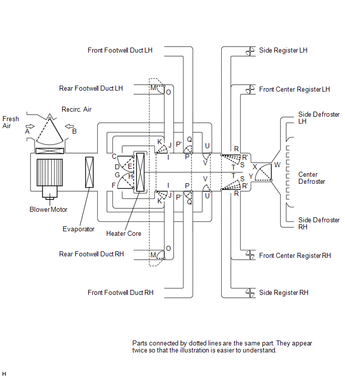 Functions of Main Dampers: Functions of Main Dampers:
|
Control Damper
|
Operation Position
|
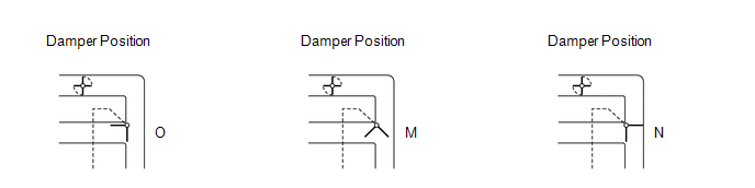
Damper Position
|
Operation
|
|
Air Inlet Control Damper
|
FRESH
|
B
|
Brings in fresh air.
|
|
RECIRC
|
A
|
Recirculates internal air.
|
|
Air Mix Control Damper
|
MAX COLD to MAX HOT Temperature Setting
|
C - E
F - H
I - K
|
Varies the mixture ratio of fresh air and recirculated air in order to
regulate the temperature continuously from HOT to COLD.
|
|
Cool Air Bypass Damper
|
MAX COLD to MAX HOT Temperature Setting
|
U, V
|
Cool air blows out of the front center register and side registers in
order to adjust the temperature around the head of the occupant during cooling
or warming.
|
|
Air Outlet Control Damper
|
FACE
 |
O, P, T, W
|
Air blows out of the front center register, side registers, and footwell
ducts.*1
|
|
BI-LEVEL
 |
M, P', S, W
|
Air mainly blows out of the front center register, side register, and
footwell ducts.
|
|
FOOT
 |
M, Q, R', X
|
Air mainly blows out of the front and rear footwell ducts. In addition,
air blows out slightly from the front and side defrosters, front center
register, and side register.*2
|
|
FOOT / DEF
 |
M, P', R', Y'
|
Air mainly blows out of the front and side defrosters to defrost the
windshield; air also blows out from the front and rear footwell ducts, front
center register, and side register.*2
|
|
DEF
 |
O, P, R, Y
|
Air blows out of the front and side defrosters and side registers to
defrost the windshield.
|
HINT:
*1: In multi mode, air blows out of all the air outlets except the front and
side defrosters.
*2: In multi mode, air blows out of all the air outlets.
3. MODE POSITION AND DAMPER OPERATION (for CrewMax)
(a) Mode Position and Damper Operation
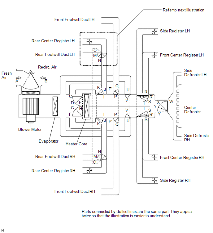
 Functions of Main Dampers: Functions of Main Dampers:
|
Control Damper
|
Operation Position
|
Damper Position
|
Operation
|
|
Air Inlet Control Damper
|
FRESH
|
B
|
Brings in fresh air.
|
|
RECIRC
|
A
|
Recirculates internal air.
|
|
Air Mix Control Damper
|
MAX COLD to MAX HOT Temperature Setting
|
C - E
F - H
I - K
|
Varies the mixture ratio of fresh air and recirculated air in order to
regulate the temperature continuously from HOT to COLD.
|
|
Cool Air Bypass Damper
|
MAX COLD to MAX HOT Temperature Setting
|
U, V
|
Cool air blows out of the front center register and side registers in
order to adjust the temperature around the head of the occupant during cooling
or warming.
|
|
Air Outlet Control Damper
|
FACE
|
O, P, T, W
|
Air blows out of the front center register, side registers, and footwell
ducts.*1
|
|
BI-LEVEL
|
M, P', S, W
|
Air mainly blows out of the front center register, side register, and
footwell ducts.
|
|
FOOT
|
M, Q, R', X
|
Air mainly blows out of the front and rear footwell ducts. In addition,
air blows out slightly from the front and side defrosters, front center
register, and side register.*2
|
|
FOOT / DEF
|
M, P', R', Y'
|
Air mainly blows out of the front and side defrosters to defrost the
windshield; air also blows out from the front and rear footwell ducts, front
center register, and side register.*2
|
|
DEF
|
N, P, R, Y
|
Air blows out of the front and side defrosters and side registers to
defrost the windshield.
|
HINT:
*1: In multi mode, air blows out of all the air outlets except the front and
side defrosters.
*2: In multi mode, air blows out of all the air outlets.
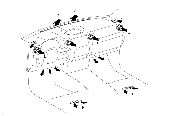
4. AIR OUTLETS AND AIRFLOW VOLUME (for Double Cab)
(a) Air Outlets and Airflow Volume
|
INDICATION
(MODE)
|
FACE
|
FOOT
|
DEF
|
|
CENTER
|
SIDE
|
FRONT
|
REAR
|
CENTER
|
SIDE
|
|
Driver Side
|
Passenger Side
|
Driver Side
|
Passenger Side
|
Driver Side
|
Passenger Side
|
Driver Side
|
Passenger Side
|
Driver Side
|
Passenger Side
|
Driver Side
|
Passenger Side
|
|
C
|
B
|
D
|
A
|
G
|
E
|
H
|
F
|
K
|
J
|
L
|
I
|
|
FACE1
|
 |
|
|
|
-
|
-
|
-
|
-
|
-
|
-
|
-
|
-
|
|
FACE2
|
 |
|
|
|
 |
|
|
|
-
|
-
|
-
|
-
|
|
B/L
|
 |
|
|
|
 |
|
|
|
-
|
-
|
-
|
-
|
|
FOOT-D
|
 |
|
|
|
|
|
|
|
|
|
|
|
|
FOOT-R
|
|
|
|
|
 |
|
|
|
|
|
|
|
|
FOOT-F
|
|
|
|
|
|
|
|
|
|
|
|
|
|
F/D
|
|
|
|
|
|
|
|
|
|
|
|
|
|
DEF
|
-
|
-
|
-
|
-
|
-
|
-
|
-
|
-
|
|
|
|
|
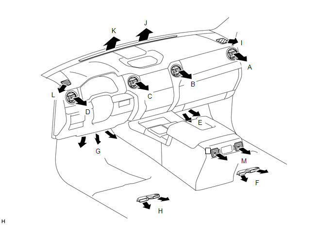
5. AIR OUTLETS AND AIRFLOW VOLUME (for CrewMax)
(a) Air Outlets and Airflow Volume
|
INDICATION
(MODE)
|
FACE
|
FOOT
|
DEF
|
|
CENTER
|
SIDE
|
REAR
|
FRONT
|
REAR
|
CENTER
|
SIDE
|
|
Driver Side
|
Passenger Side
|
Driver Side
|
Passenger Side
|
-
|
Driver Side
|
Passenger Side
|
Driver Side
|
Passenger Side
|
Driver Side
|
Passenger Side
|
Driver Side
|
Passenger Side
|
|
C
|
B
|
D
|
A
|
M
|
G
|
E
|
H
|
F
|
K
|
J
|
L
|
I
|
|
FACE1
|
|
|
|
|
|
-
|
-
|
-
|
-
|
-
|
-
|
-
|
-
|
|
FACE2
|
|
|
|
|
|
|
|
|
|
-
|
-
|
-
|
-
|
|
B/L
|
|
|
|
|
|
|
|
|
|
-
|
-
|
-
|
-
|
|
FOOT-D
|
|
|
|
|
|
|
|
|
|
|
|
|
|
|
FOOT-R
|
|
|
|
|
|
|
|
|
|
|
|
|
|
|
FOOT-F
|
|
|
|
|
|
|
|
|
|
|
|
|
|
|
F/D
|
|
|
|
|
|
|
|
|
|
|
|
|
|
|
DEF
|
-
|
-
|
-
|
-
|
-
|
-
|
-
|
-
|
-
|
|
|
|
|
|


