DESCRIPTION The No. 1 cooler thermistor is installed on the evaporator in the air conditioner unit to detect the cooled air temperature that has passed through the evaporator and control the air conditioning. It sends appropriate signals to the air conditioning amplifier. The resistance of the No. 1 cooler thermistor changes in accordance with the cooled air temperature that has passed through the evaporator. As the temperature decreases, the resistance increases. As the temperature increases, the resistance decreases. The air conditioning amplifier applies voltage (5 V) to the No. 1 cooler thermistor and reads voltage changes as the resistance of the No. 1 cooler thermistor changes. This sensor is used for frost prevention.
WIRING DIAGRAM 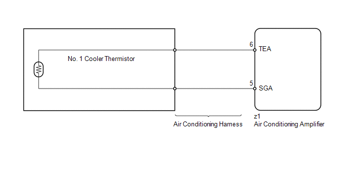
PROCEDURE
(a) Use the Data List to check if the No. 1 cooler thermistor is functioning properly. Air Conditioner
OK: The display is as specified in the normal condition. Result
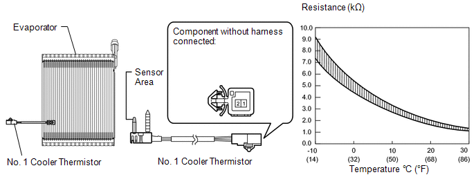
(a) Remove the No. 1 cooler thermistor connector (see page
(b) Measure the resistance according to the value(s) in the table below. Standard resistance:
NOTICE:
HINT: As the temperature increases, the resistance decreases (see the graph).
(a) Repair or replace the air conditioning harness.
(a) Clear the DTC (see page (b) Check for DTC (see page OK: DTC is not output.
|
Toyota Tundra Service Manual > Cruise Control System: Road Test
ROAD TEST PROBLEM SYMPTOM CONFIRMATION (a) Inspect the SET function. (1) Turn the cruise control system on using the cruise control main switch (ON-OFF button). *a ON-OFF (2) Check that the cruise control indicator illuminates in the combination meter assembly. (3) Drive at a speed between approxima ...


 ).
).
