DESCRIPTION This circuit provides power to operate the air conditioning amplifier. WIRING DIAGRAM 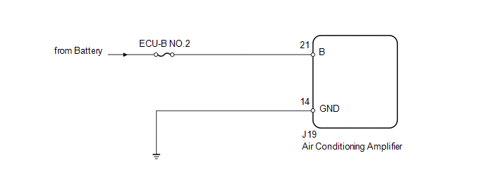
PROCEDURE
(a) Remove the ECU-B NO.2 fuse from the driver side junction block. (b) Measure the resistance according to the value(s) in the table below. Standard resistance:
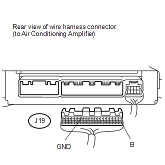
(a) Disconnect the J19 air conditioning amplifier connector. (b) Measure the resistance and voltage according to the value(s) in the table below. Standard resistance:
Standard voltage:
|
Toyota Tundra Service Manual > Sfi System: Brake Switch "B" Circuit High (P0724)
DESCRIPTION The purpose of this circuit is to prevent the engine from stalling while driving in the lock-up condition when the brakes are suddenly applied. When the brake pedal is depressed, this switch sends a signal to the ECM. Then the ECM cancels the operation of the lock-up clutch while braking ...


