DESCRIPTION When the ignition switch is turned ON, positive (+) battery voltage is applied to the air conditioning amplifier. WIRING DIAGRAM 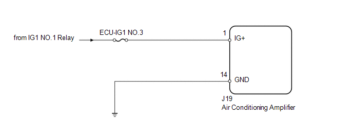
PROCEDURE
(a) Remove the ECU-IG1 NO.3 fuse from the driver side junction block. (b) Measure the resistance according to the value(s) in the table below. Standard resistance:
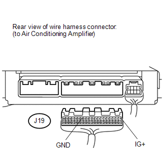
(a) Disconnect the J19 air conditioning amplifier connector. (b) Measure the resistance and voltage according to the value(s) in the table below. Standard resistance:
Standard voltage:
|
Toyota Tundra Service Manual > Front Power Seat Control System(w/ Memory): Data List / Active Test
DATA LIST / ACTIVE TEST 1. DATA LIST HINT: Using the Techstream to read the Data List allows the values or states of switches, sensors, actuators and other items to be read without removing any parts. This non-intrusive inspection can be very useful because intermittent conditions or signals may be ...


