SYSTEM DIAGRAM 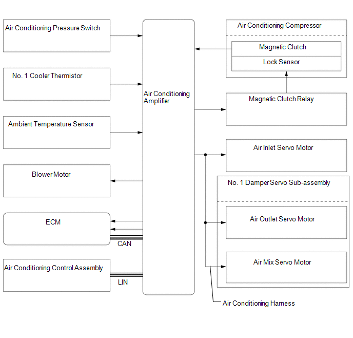 Communication table Communication table
|
Toyota Tundra Owners Manual > Instrument cluster: Multi-information display
Display contents The multi-information display presents the driver with a variety of vehicle data. Menu icons Displays the following information when an icon is selected. Some of the information may be displayed automatically depending on the situation. Drive information Select to display various dr ...


