REMOVAL PROCEDURE 1. RECOVER REFRIGERANT FROM REFRIGERATION SYSTEM (a) for HFC-134a(R134a): Click here (b) for HFO-1234yf(R1234yf): Click here 2. DRAIN ENGINE COOLANT (a) for 1UR-FE: Click here (b) for 3UR-FE: Click here (c) for 3UR-FBE: Click here 3. PRECAUTION NOTICE: After turning the ignition switch off, waiting time may be required before disconnecting the cable from the battery terminal. Therefore, make sure to read the disconnecting the cable from the battery terminal notice before proceeding with work. Click here 4. DISCONNECT CABLE FROM NEGATIVE BATTERY TERMINAL CAUTION: Wait at least 90 seconds after disconnecting the cable from the negative (-) battery terminal to disable the SRS system. NOTICE: When disconnecting the cable, some systems need to be initialized after the cable is reconnected. Click here 5. REMOVE NO. 2 COOLER COVER 
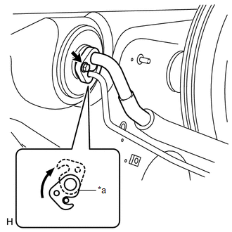
(a) Remove the 2 nuts. (b) Detach the 2 claws and remove the No. 2 cooler cover. 6. DISCONNECT SUCTION PIPE SUB-ASSEMBLY AND AIR CONDITIONER TUBE ASSEMBLY (for HFC-134a(R134a))
(b) Detach the plate as shown in the illustration. (c) Disconnect the suction pipe sub-assembly and air conditioner tube assembly. NOTICE:
(d) Remove the 2 O-rings from the suction pipe sub-assembly and liquid tube. 7. DISCONNECT AIR CONDITIONING TUBE ASSEMBLY (for HFO-1234yf(R1234yf))
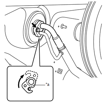
(b) Detach the plate as shown in the illustration. (c) Disconnect the air conditioning tube assembly. NOTICE:
(d) Remove the 2 O-rings from the air conditioning tube assembly. 8. DISCONNECT INLET HEATER WATER HOSE AND OUTLET HEATER WATER HOSE 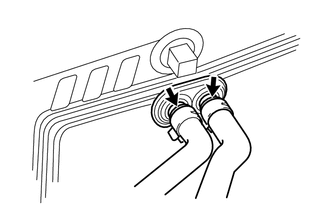
(a) Using pliers, grip the claws of the clip and slide the clip. (b) Disconnect the inlet heater water hose and outlet heater water hose. 9. REMOVE FRONT WIPER MOTOR AND BRACKET Click here 10. REMOVE STEERING COLUMN ASSEMBLY Click here 11. REMOVE INSTRUMENT PANEL SUB-ASSEMBLY (a) for Column Shift Type: Click here (b) for Floor Shift Type: Click here 12. REMOVE INSTRUMENT PANEL REINFORCEMENT ASSEMBLY (a) Disconnect the clamps, connectors and wire harness. (b) Remove the 11 bolts and 4 nuts. 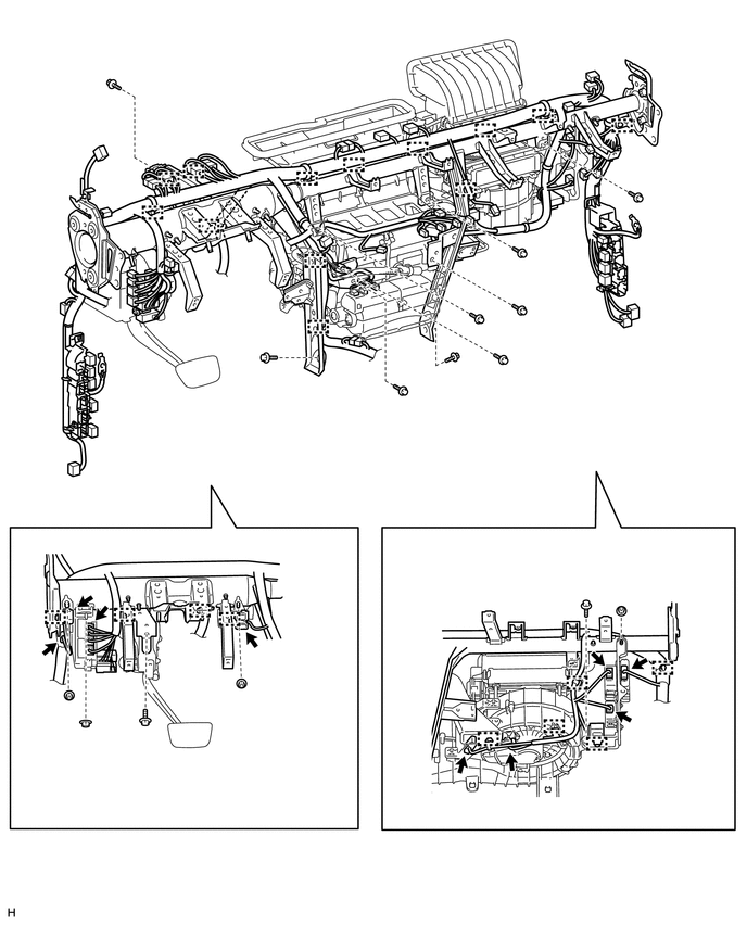
(c) Remove the instrument panel reinforcement assembly. (1) for Driver Side: Remove the 2 caps and 3 bolts. 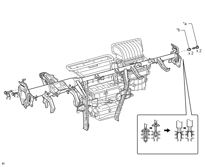
(2) for Passenger Side: Using a T40 "TORX" socket, remove the 2 "TORX" bolts. HINT: When removing the bolts, the collars may come off with the bolts. (3) for Passenger Side: Using a 12 mm hexagon wrench, remove the 2 collars. 13. REMOVE REAR NO. 1 AIR DUCT
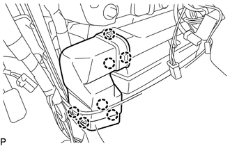
14. REMOVE REAR NO. 3 AIR DUCT
15. REMOVE AIR CONDITIONING UNIT (a) Remove the nut and air conditioning unit. 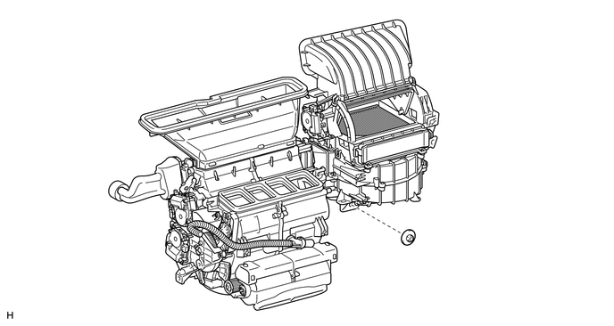 |
Toyota Tundra Service Manual > Cruise Control System: Cruise Control Input Circuit (P0575)
DESCRIPTION This DTC is stored when there is a malfunction in the ECM. DTC No. Detection Item DTC Detection Condition Trouble Area P0575 Cruise Control Input Circuit While the cruise control system is operating, the cruise control system control of vehicle speed is not canceled and approximately 0.4 ...