INSTALLATION PROCEDURE 1. ADJUST COMPRESSOR OIL (a) When replacing the compressor and magnetic clutch with a new one, gradually discharge the refrigerant gas from the service valve, and drain the following amount of oil from the new compressor and magnetic clutch before installation. Standard: (Oil capacity inside the new compressor and magnetic clutch: 140 to 155 cc (4.73 to 5.24 fl.oz)) - (Remaining oil amount in the removed compressor and magnetic clutch) = (Oil amount to be removed from the new compressor when replacing) NOTICE:
2. INSTALL COOLER COMPRESSOR ASSEMBLY
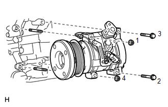
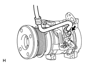
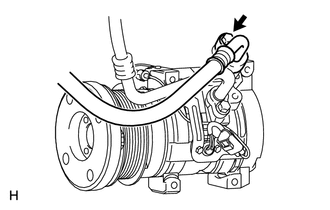
(b) Install the 2 bolts and 2 nuts. Torque: 24.5 N·m {250 kgf·cm, 18 ft·lbf} HINT: Tighten the bolts and nuts in the order shown in the illustration to install the cooler compressor assembly. (c) Connect the connector. 3. CONNECT NO. 1 COOLER REFRIGERANT SUCTION HOSE (a) Remove the attached vinyl tape from the No. 1 cooler refrigerant suction hose. (b) Sufficiently apply compressor oil to a new O-ring and the fitting surface of the cooler compressor assembly. Compressor oil: ND-OIL 12 or equivalent (c) Install the O-ring to the No. 1 cooler refrigerant suction hose.
4. CONNECT NO. 1 COOLER REFRIGERANT DISCHARGE HOSE (a) Remove the attached vinyl tape from the No. 1 cooler refrigerant discharge hose. (b) Sufficiently apply compressor oil to a new O-ring and the fitting surface of the cooler compressor assembly. Compressor oil: ND-OIL 12 or equivalent (c) Install the O-ring to the No. 1 cooler refrigerant discharge hose.
5. INSTALL FAN AND GENERATOR V BELT (a) for 1UR-FE: Click here (b) for 3UR-FE: Click here (c) for 3UR-FBE: Click here 6. INSTALL FRONT FENDER APRON SEAL LH
7. CHARGE REFRIGERANT (for HFC-134a(R134a)) Click here 8. CHARGE AIR CONDITIONING SYSTEM WITH REFRIGERANT (for HFO-1234yf(R1234yf)) Click here 9. WARM UP ENGINE (a) for HFC-134a(R134a): Click here (b) for HFO-1234yf(R1234yf): Click here 10. CHECK FOR REFRIGERANT GAS LEAK (for HFC-134a(R134a)) Click here 11. INSPECT FOR REFRIGERANT LEAK (for HFO-1234yf(R1234yf)) Click here |
Toyota Tundra Service Manual > Airbag System: Side Airbag Sensor RH (B1690,B1695)
DESCRIPTION The side airbag sensor assembly LH or RH consists of a lateral deceleration sensor, etc. If the airbag sensor assembly receives signals from the lateral deceleration sensor, it determines whether the SRS should be activated. DTC B1690 or B1695 is stored when a malfunction is detected in ...