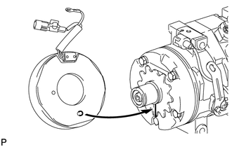
REASSEMBLY PROCEDURE 1. INSTALL MAGNET CLUTCH ASSEMBLY
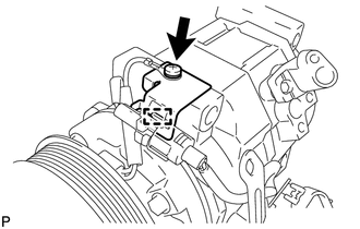
(c) Connect the connector.
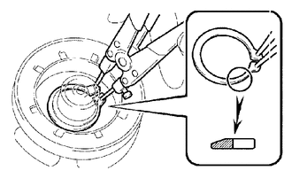
(e) Install the magnet clutch washer(s) and magnet clutch hub. NOTICE: Do not change the combination of the magnet clutch washer(s) used before disassembly.
2. INSTALL COOLER COMPRESSOR BRACKET
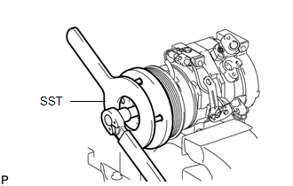
(b) Attach the harness clamp. 3. INSPECT MAGNET CLUTCH CLEARANCE
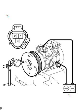
(b) Set the dial indicator to the magnet clutch hub. (c) Connect the battery positive lead to terminal 3 of the magnet clutch connector and the negative lead to the ground wire. Turn the magnet clutch on and off and measure the clearance. Standard clearance: 0.35 to 0.60 mm (0.014 to 0.024 in.) Text in Illustration
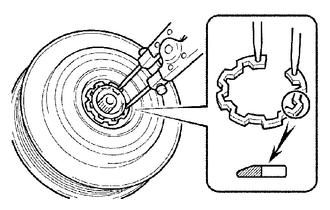
If the measured value is not within the standard clearance, remove the magnet clutch hub and adjust the clearance using magnet clutch washers to obtain the standard clearance. Magnet clutch washer thickness: 0.1 mm (0.004 in.) 0.3 mm (0.012 in.) 0.5 mm (0.020 in.) NOTICE: Adjustment should be performed with 3 or fewer magnet clutch washers. (d) Remove the cooler compressor assembly from the vise. |
Toyota Tundra Service Manual > Propeller Shaft Assembly(for 4wd): Inspection
INSPECTION CAUTION / NOTICE / HINT PROCEDURE 1. INSPECT PROPELLER SHAFT WITH CENTER BEARING ASSEMBLY (a) Using a dial indicator, measure the intermediate shaft runout. Maximum runout: 0.61 mm (0.0240 in.) If the intermediate shaft runout is more than the maximum, replace the propeller shaft with cen ...