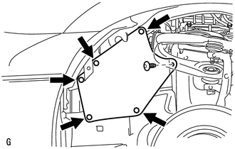
REMOVAL PROCEDURE 1. RECOVER REFRIGERANT FROM REFRIGERATION SYSTEM (a) for HFC-134a(R134a): Click here (b) for HFO-1234yf(R1234yf): Click here 2. REMOVE FRONT FENDER APRON SEAL LH
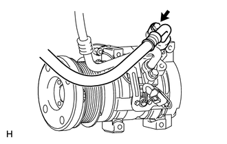
3. REMOVE FAN AND GENERATOR V BELT (a) for 1UR-FE: Click here (b) for 3UR-FE: Click here (c) for 3UR-FBE: Click here 4. DISCONNECT NO. 1 COOLER REFRIGERANT DISCHARGE HOSE
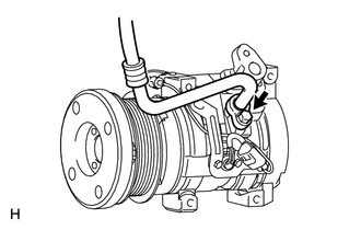
(b) Remove the O-ring from the No. 1 cooler refrigerant discharge hose. NOTICE: Seal the openings of the disconnected parts using vinyl tape to prevent moisture and foreign matter from entering them. 5. DISCONNECT NO. 1 COOLER REFRIGERANT SUCTION HOSE
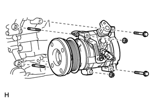
(b) Remove the O-ring from the No. 1 cooler refrigerant suction hose. NOTICE: Seal the openings of the disconnected parts using vinyl tape to prevent moisture and foreign matter from entering them. 6. REMOVE COOLER COMPRESSOR ASSEMBLY
(b) Remove the 2 bolts and 2 nuts. (c) Remove the 2 stud bolts and cooler compressor assembly. |
Toyota Tundra Owners Manual > Bluetooth phone: Using a Bluetooth
phone
The hands-free system is a function that allows you to use your cellular phone without touching it. This system supports Bluetooth. Bluetooth is a wireless data system that allows the cellular phone to wirelessly connect to the hands-free system and make/receive calls. Before making a phone call, c ...