DESCRIPTION This DTC is
stored when a communication error occurs between the radio and display
receiver assembly and combination meter assembly. |
DTC Code | DTC Detection Condition |
Trouble Area | | B1324 |
After
the radio and display receiver assembly receives a registration
information signal, which is sent by the combination meter assembly when
the ignition switch is ACC, 1 or more times, the radio and display
receiver assembly cannot receive the signal for 30 seconds or more. |
- Combination meter assembly
- Radio and display receiver assembly
- Harness or connector
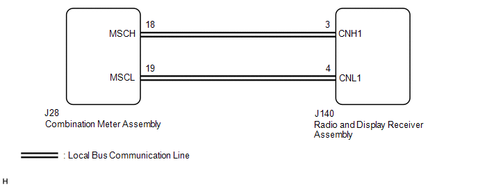
| WIRING DIAGRAM
 CAUTION / NOTICE / HINT
NOTICE: When replacing the combination meter assembly, make sure to replace it with a new one. PROCEDURE
| 1. |
CHECK HARNESS AND CONNECTOR (RADIO AND DISPLAY RECEIVER ASSEMBLY - COMBINATION METER ASSEMBLY) |
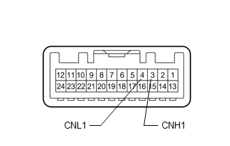
(a) Disconnect the J140 radio and display receiver assembly connector.
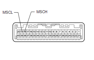
(b) Disconnect the J28 combination meter assembly connector. (c) Measure the resistance according to the value(s) in the table below.
Standard Resistance: |
Tester Connection | Condition |
Specified Condition | |
J140-3 (CNH1) - J28-18 (MSCH) |
Always | Below 1 Ω | |
J140-4 (CNL1) - J28-19 (MSCL) |
Always | Below 1 Ω | |
J140-3 (CNH1) - Body ground |
Always | 10 kΩ or higher | |
J140-4 (CNL1) - Body ground |
Always | 10 kΩ or higher | |
J140-3 (CNH1) - J140-4 (CNL1) |
Always | 10 kΩ or higher |
(d) Measure the voltage according to the value(s) in the table below. Standard Voltage: |
Tester Connection | Condition |
Specified Condition | |
J140-3 (CNH1) - Body ground |
Always | Below 1 V | |
J140-4 (CNL1) - Body ground |
Always | Below 1 V |
| NG |
 | REPAIR OR REPLACE HARNESS OR CONNECTOR |
|
OK |
 | |
| 2. |
INSPECT COMBINATION METER ASSEMBLY | (a) Remove the combination meter assembly.
See page 
| (b) Measure the resistance according to the value(s) in the table below.
Standard Resistance: |
Tester Connection | Condition |
Specified Condition | |
18 (MSCH) - 19 (MSCL) |
Always | 108 to 132 Ω | |
|
| NG |
| REPLACE COMBINATION METER ASSEMBLY |
|
OK | |
| |
| 3. |
INSPECT RADIO AND DISPLAY RECEIVER ASSEMBLY |
(a) Remove the radio and display receiver assembly. for Column Shift Type: See page
for Floor Shift Type: See page
| (b) Measure the resistance according to the value(s) in the table below.
Standard Resistance: |
Tester Connection | Condition |
Specified Condition | |
3 (CNH1) - 4 (CNL1) |
Always | 108 to 132 Ω | |
|
|
Result | Proceed to | |
OK | A | |
NG (for Column Shift Type) |
B | | NG (for Floor Shift Type) |
C |
| B |
| REPLACE RADIO AND DISPLAY RECEIVER ASSEMBLY |
| C |
| REPLACE RADIO AND DISPLAY RECEIVER ASSEMBLY |
|
A | |
| |
| 4. |
CHECK COMBINATION METER ASSEMBLY | (a) Replace the combination meter assembly.
See page (b) Clear the DTCs. See page
(c) Check for DTCs. See page
OK: No DTCs are output.
|
Result | Proceed to | |
OK | A | |
NG (for Column Shift Type) |
B | | NG (for Floor Shift Type) |
C |
| A |
| END (COMBINATION METER ASSEMBLY IS DEFECTIVE) |
| B |
| REPLACE RADIO AND DISPLAY RECEIVER ASSEMBLY |
| C |
| REPLACE RADIO AND DISPLAY RECEIVER ASSEMBLY | |