INSPECTION PROCEDURE 1. INSPECT FRONT DOOR LOCK ASSEMBLY LH (a) Check the door lock motor. (1) Apply battery voltage to the door lock motor and check operation of the door lock motor. 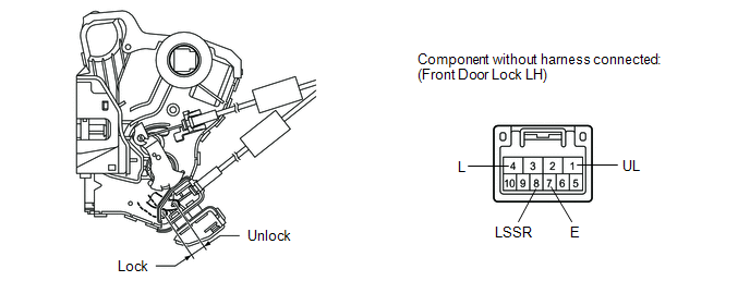
OK:
(b) Check the door lock position switch. (1) Measure the resistance according to the value(s) in the table below. Standard resistance:
(c) Check the door lock and unlock switch. (1) Measure the resistance according to the value(s) in the table below. 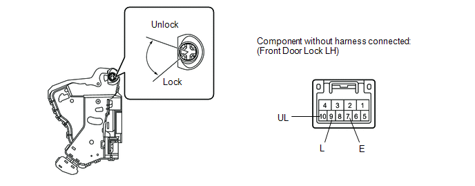
Standard resistance:
2. INSPECT FRONT DOOR LOCK ASSEMBLY RH (a) Check the door lock motor. (1) Apply battery voltage to the door lock motor and check operation of the door lock motor. 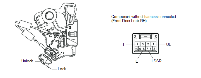
OK:
(b) Check the door lock position switch. (1) Measure the resistance according to the value(s) in the table below. Standard resistance:
|
Toyota Tundra Service Manual > Audio And Visual System: Data Signal Circuit between Radio Receiver and Stereo Jack Adapter
DESCRIPTION The No. 1 stereo jack adapter assembly sends the sound data signal or image data signal from a device to the radio and display receiver assembly via this circuit. WIRING DIAGRAM PROCEDURE 1. CHECK HARNESS AND CONNECTOR (RADIO AND DISPLAY RECEIVER ASSEMBLY - NO. 1 STEREO JACK ADAPTER ASSE ...


