SYSTEM DIAGRAM 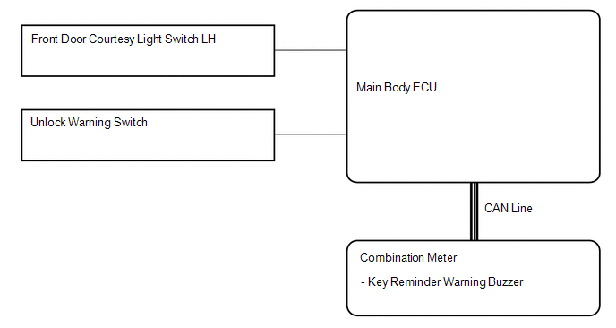 Communication table: Communication table:
|
Toyota Tundra Service Manual > Airbag System: Short in D Squib Circuit (B1800-B1803)
DESCRIPTION The driver side squib circuit consists of the airbag sensor assembly, spiral with sensor cable sub-assembly and horn button assembly. The circuit instructs the SRS to deploy when deployment conditions are met. These DTCs are stored when a malfunction is detected in the driver side squib ...


