DESCRIPTION
When an open or short circuit is detected in the transponder key amplifier built
into the transponder key ECU assembly, the transponder key ECU assembly stores this
DTC.
|
DTC No.
|
Detection Item
|
DTC Detection Condition
|
Trouble Area
|
Note
|
|
B2784
|
Antenna Coil Open / Short
|
The antenna coil in the transponder key coil is open/shorted (1 trip
detection logic*).
|
- Harness or connector
- Transponder key coil
- Transponder key ECU assembly
|
- Insert the key into the ignition key cylinder.
|
- *: Only output while a malfunction is present.
Vehicle Condition and Fail-safe Operation when Malfunction Detected
|
Vehicle Condition when Malfunction Detected
|
Fail-safe Operation when Malfunction Detected
|
|
Engine cannot be started
|
-
|
Related Data List and Active Test
|
DTC No.
|
Data List and Active Test
|
|
B2784
|
Antenna Coil Status
|
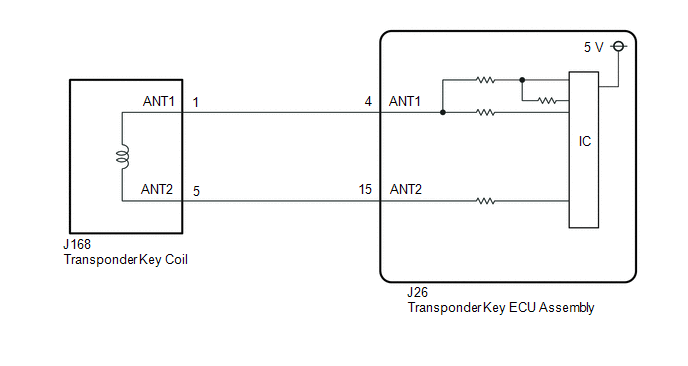
WIRING DIAGRAM
CAUTION / NOTICE / HINT
NOTICE:
- If the transponder key ECU assembly is replaced, refer to Registration.
Click here 
- After repair, confirm that no DTCs are output by performing "DTC Output
Confirmation Operation".
PROCEDURE
(a) Clear the DTCs.
Click here
| NEXT |

|
|
(a) Check for DTCs.
Click here
HINT:
Before checking for DTCs, perform the "DTC Output Confirmation Operation" procedure.
OK:
DTC B2784 is not output.
|
Result
|
Proceed to
|
|
B2784 is not output
|
A
|
|
B2784 is output
|
B
|
| A |
 |
USE SIMULATION METHOD TO CHECK
|
| B |
|
|
|
|
3.
|
CHECK CONNECTION OF CONNECTOR
|
(a) Check that the connectors are properly connected to the transponder key coil.
| NEXT |
|
|
|
(a) Clear the DTCs.
Click here
| NEXT |
|
|
|
(a) Check for DTCs.
Click here
HINT:
Before checking for DTCs, perform "DTC Output Confirmation Operation" procedure.
OK:
DTC B2784 is not output.
|
Result
|
Proceed to
|
|
B2784 is not output
|
A
|
|
B2784 is output
|
B
|
| A |
|
END (CONNECTOR WAS NOT CONNECTED PROPERLY)
|
| B |
|
|
|
|
6.
|
CHECK TRANSPONDER KEY COIL (OUTPUT)
|
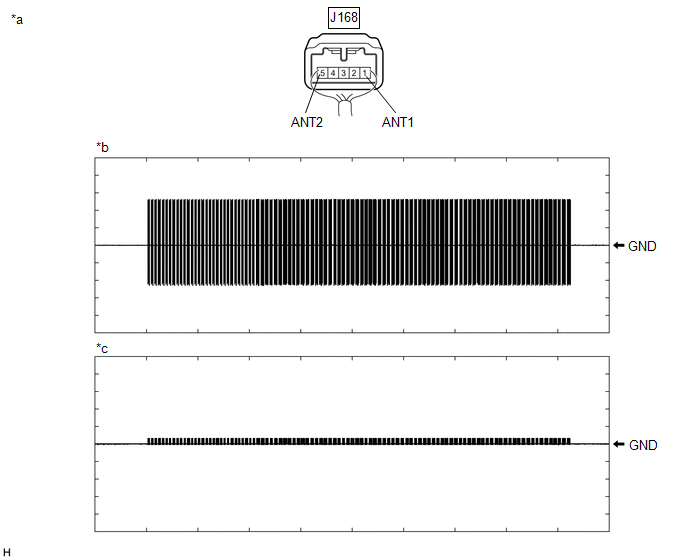
(a) Using an oscilloscope, check the waveform.
|
*a
|
Component with harness connected
(Transponder Key Coil)
|
*b
|
Waveform 1
|
|
*c
|
Waveform 2
|
-
|
-
|
Waveform 1
|
Item
|
Content
|
|
Tester Connection
|
J168-1 (ANT1) - Body ground
|
|
Tool Setting
|
20 V/DIV., 2 s./DIV.
|
|
Condition
|
Within 3 seconds of inserting key into ignition key cylinder
|
Waveform 2
|
Item
|
Content
|
|
Tester Connection
|
J168-5 (ANT2) - Body ground
|
|
Tool Setting
|
20 V/DIV., 2 s./DIV.
|
|
Condition
|
Within 3 seconds of inserting key into ignition key cylinder
|
OK:
Waveform is similar to that shown in the illustration.
| OK |
|
REPLACE TRANSPONDER KEY COIL
|
| NG |
|
|
|
|
7.
|
CHECK HARNESS AND CONNECTOR (TRANSPONDER KEY ECU ASSEMBLY - TRANSPONDER
KEY COIL AND BODY GROUND)
|
(a) Disconnect the J26 transponder key ECU assembly connector.
(b) Disconnect the J168 transponder key coil connector.
(c) Measure the resistance according to the value(s) in the table below.
Standard Resistance:
|
Tester Connection
|
Condition
|
Specified Condition
|
|
J26-4 (ANT1) - J168-1 (ANT1)
|
Always
|
Below 1 Ω
|
|
J26-15 (ANT2) - J168-5 (ANT2)
|
Always
|
Below 1 Ω
|
|
J26-4 (ANT1) - Body ground
|
Always
|
10 kΩ or higher
|
|
J168-1 (ANT1) - Body ground
|
Always
|
10 kΩ or higher
|
|
J26-15 (ANT2) - Body ground
|
Always
|
10 kΩ or higher
|
|
J168-5 (ANT2) - Body ground
|
Always
|
10 kΩ or higher
|
| NG |
|
REPAIR OR REPLACE HARNESS OR CONNECTOR
|
| OK |
|
|
|
|
8.
|
REPLACE TRANSPONDER KEY ECU ASSEMBLY
|
(a) Replace the transponder key ECU assembly with a new one.
Click here
NOTICE:
Key ID code registration is necessary when replacing the transponder key ECU
assembly.
Click here
| NEXT |
|
|
|
(a) Clear the DTCs.
Click here
| NEXT |
|
|
|
(a) Check for DTCs.
Click here
HINT:
Before checking for DTCs, perform the "DTC Output Confirmation Operation" procedure.
OK:
DTC B2784 is not output.
|
Result
|
Proceed to
|
|
B2784 is not output
|
A
|
|
B2784 is output
|
B
|
| A |
|
END (TRANSPONDER KEY ECU ASSEMBLY WAS DEFECTIVE)
|
| B |
|
REPLACE TRANSPONDER KEY COIL
|
| 

