TERMINALS OF ECU
CHECK TRANSPONDER KEY ECU ASSEMBLY
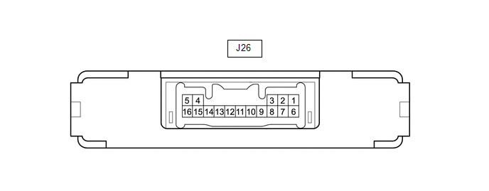
(a) Disconnect the J26 transponder key ECU assembly connector.
(b) Measure the resistance and voltage according to the value(s) in the table
below.
HINT:
Measure the values on the wire harness side with the connector disconnected.
|
Tester Connection
|
Input/Output
|
Wiring Color
|
Terminal Description
|
Condition
|
Specified Condition
|
Related Data List Item
|
|
J26-5 (GND) - Body ground
|
-
|
W-B - Body ground
|
Ground
|
Always
|
Below 1 Ω
|
-
|
|
J26-1 (+B) - J26-5 (GND)
|
Input
|
G - W-B
|
Battery
|
Always
|
11 to 14 V
|
+B
|
|
J26-2 (IG) - J26-5 (GND)
|
Input
|
L - W-B
|
Ignition switch
|
Ignition switch off
|
Below 1 V
|
IG SW
|
|
Ignition switch ON
|
11 to 14 V
|
|
J26-3 (KSW) - J26-5 (GND)
|
Input
|
B - W-B
|
Unlock warning switch signal
|
No key in ignition key cylinder
|
10 kΩ or higher
|
Key SW/B2780
|
|
Key in ignition key cylinder
|
Below 1 Ω
|
(c) Reconnect the J26 transponder key ECU assembly connector.
(d) Measure the voltage and check for pulses according to the value(s) in the
table below.
|
Tester Connection
|
Input/Output
|
Wiring Color
|
Terminal Description
|
Condition
|
Specified Condition
|
Related Data List Item
|
|
J26-8 (IND) - J26-5 (GND)
|
Output
|
V - W-B
|
Security indicator light signal
|
No key in ignition key cylinder, or 20 seconds elapsed after turning
ignition switch to ACC or off (engine immobiliser system set)
|
Pulse generation
|
Immobiliser
|
|
Key in ignition key cylinder (engine immobiliser system unset)
|
Below 1 V
|
|
J26-9 (D) - J26-5 (GND)
|
Input/Output
|
BE - W-B
|
DLC3 communication
|
Without communication
|
Below 1 V
|
-
|
|
During communication
|
Pulse generation
|
|
J26-4 (ANT1) - J26-5 (GND)
|
Input/Output
|
LG - W-B
|
Transponder key amplifier power source
|
No key in ignition key cylinder
|
4 to 6 V
|
-
|
|
Within 3 seconds of inserting key into ignition key cylinder
|
Pulse generation
(See waveform 1)
|
|
J26-15 (ANT2) - J26-5 (GND)
|
Input/Output
|
V - W-B
|
Transponder key amplifier communication signal
|
No key in ignition key cylinder
|
4 to 6 V
|
-
|
|
Within 3 seconds of inserting key into ignition key cylinder
|
Pulse generation
(See waveform 2)
|
|
J26-12 (EFII) - J26-5 (GND)
|
Input
|
R - W-B
|
ECM input signal
|
Within 3 seconds of starter operation and initial combustion, or within
3 seconds of ignition switch first being turned to ON after cable disconnected
and reconnected to negative (-) battery terminal
|
Pulse generation
(See waveform 3)
|
E/G Start Permission
|
|
J26-13 (EFIO) - J26-5 (GND)
|
Output
|
G - W-B
|
ECM output signal
|
Ignition switch off
|
Below 1 V
|
E/G Start Permission
|
|
Within 3 seconds of starter operation and initial combustion, or within
3 seconds of ignition switch first being turned to ON after cable disconnected
and reconnected to negative (-) battery terminal
|
Pulse generation
(See waveform 4)
|
(e) Using an oscilloscope, check the waveform.
(1) Waveform 1 (Reference)
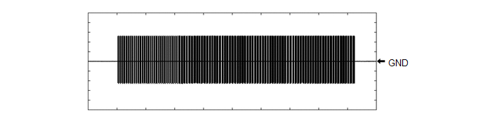
|
Tester Connection
|
J26-4 (ANT1) - J26-5 (GND)
|
|
Tool Setting
|
20 V/DIV., 2 s./DIV.
|
|
Condition
|
Within 3 seconds of inserting key into ignition key cylinder
|
(2) Waveform 2 (Reference)

|
Tester Connection
|
J26-15 (ANT2) - J26-5 (GND)
|
|
Tool Setting
|
20 V/DIV., 2 s./DIV.
|
|
Condition
|
Within 3 seconds of inserting key into ignition key cylinder
|
(3) Waveform 3 (Reference)
|
*a
|
Approximately 160 ms
|
*b
|
Approximately 510 ms
|
|
Tester Connection
|
J26-12 (EFII) - J26-5 (GND)
|
|
Tool Setting
|
2 V/DIV., 500 ms./DIV.
|
|
Condition
|
Within 3 seconds of starter operation and initial combustion, or within
3 seconds of ignition switch first being turned to ON after cable disconnected
and reconnected to negative (-) battery terminal
|
(4) Waveform 4 (Reference)
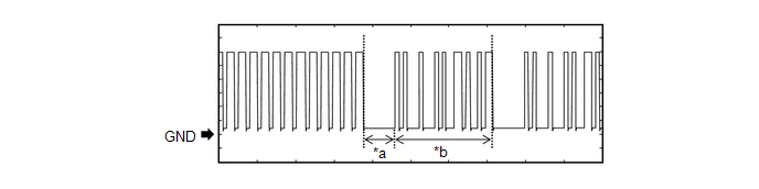
|
*a
|
Approximately 160 ms
|
*b
|
Approximately 510 ms
|
|
Tester Connection
|
J26-13 (EFIO) - J26-5 (GND)
|
|
Tool Setting
|
2 V/DIV., 500 ms./DIV.
|
|
Condition
|
Within 3 seconds of starter operation and initial combustion, or within
3 seconds of ignition switch first being turned to ON after cable disconnected
and reconnected to negative (-) battery terminal
|
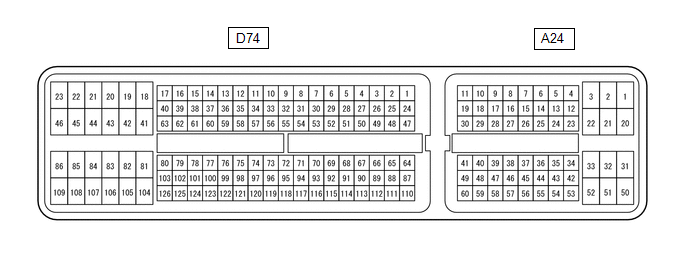
HINT:
The standard voltage between each pair of ECM terminals is shown in the table
below. The appropriate conditions for checking each pair of terminals are also indicated.
The result of checks should be compared with the standard voltage for that pair
of terminals, displayed in the "Specified Condition" column. The illustration above
can be used as a reference to identify the ECM terminal locations.
CHECK ECM
(a) Measure the resistance, voltage and check for pulses according to the value(s)
in the table below.
|
Tester Connection
|
Input/Output
|
Wiring Color
|
Terminal Description
|
Condition
|
Specified Condition
|
Related Data List Item
|
|
A24-29 (IMO) - D74-81 (E1)*1
A24-48 (IMO) - D74-81 (E1)*2
|
Output
|
P - BR
|
Transponder key ECU assembly output signal
|
Ignition switch off
|
11 to 14 V
|
E/G Start Permission
|
|
Within 3 seconds of starter operation and initial combustion, or within
3 seconds of ignition switch first being turned to ON after cable disconnected
and reconnected to negative (-) battery terminal
|
Pulse generation
(See waveform 1)
|
E/G Start Permission
|
|
A24-40 (IMI) - D74-81 (E1)*1
A24-46 (IMI) - D74-81 (E1)*2
|
Input
|
B - BR
|
Transponder key ECU assembly input signal
|
Ignition switch off
|
Below 1 V
|
E/G Start Permission
|
|
Within 3 seconds of starter operation and initial combustion, or within
3 seconds of ignition switch first being turned to ON after cable disconnected
and reconnected to negative (-) battery terminal
|
Pulse generation
(See waveform 2)
|
E/G Start Permission
|
- *1: for 1UR-FE
- *2: for 3UR-FE, 3UR-FBE
(b) Using an oscilloscope, check the waveform.
(1) Waveform 1 (Reference)
|
*a
|
Approximately 160 ms
|
*b
|
Approximately 510 ms
|
|
Tester Connection
|
A24-29 (IMO) - D74-81 (E1)*1
A24-48 (IMO) - D74-81 (E1)*2
|
|
Tool Setting
|
2 V/DIV., 500 ms./DIV.
|
|
Condition
|
Within 3 seconds of starter operation and initial combustion, or within
3 seconds of ignition switch first being turned to ON after cable disconnected
and reconnected to negative (-) battery terminal
|
- *1: for 1UR-FE
- *2: for 3UR-FE, 3UR-FBE
(2) Waveform 2 (Reference)
|
*a
|
Approximately 160 ms
|
*b
|
Approximately 510 ms
|
|
Tester Connection
|
A24-40 (IMI) - D74-81 (E1)*1
A24-46 (IMI) - D74-81 (E1)*2
|
|
Tool Setting
|
2 V/DIV., 500 ms./DIV.
|
|
Condition
|
Within 3 seconds of starter operation and initial combustion, or within
3 seconds of ignition switch first being turned to ON after cable disconnected
and reconnected to negative (-) battery terminal
|
- *1: for 1UR-FE
- *2: for 3UR-FE, 3UR-FBE
|


