INSTALLATION PROCEDURE 1. INSTALL FRONT FENDER PLATE LH HINT:
Standard:
NOTICE: Do not heat the vehicle body or front fender plate LH excessively. (a) Clean the vehicle body surface. (1) Using a heat light, heat the vehicle body surface. (2) Remove the double-sided tape from the vehicle body. (3) Wipe off any tape adhesive residue with cleaner. (b) Install a new front fender plate LH. (1) Using a heat light, heat the vehicle body and a new front fender plate LH. (2) Remove the peeling paper from the face of the front fender plate LH. HINT: After removing the peeling paper, keep the exposed adhesive free from foreign matter. (3) Install the front fender plate LH in the position shown in the illustration. HINT: Press the front fender plate LH firmly to install it. 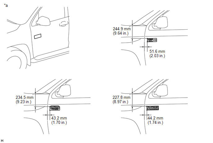 Text in Illustration Text in Illustration
2. INSTALL DOOR NAME PLATE LH HINT:
Standard:
NOTICE: Do not heat the vehicle body or door name plate LH excessively. (a) Clean the vehicle body surface. (1) Using a heat light, heat the vehicle body surface. (2) Remove the double-sided tape from the vehicle body. (3) Wipe off any tape adhesive residue with cleaner. (b) Install a new door name plate LH. (1) Using a heat light, heat the vehicle body and a new door name plate LH. (2) Remove the peeling paper from the face of the door name plate LH. HINT: After removing the peeling paper, keep the exposed adhesive free from foreign matter. (3) Install the door name plate LH in the position shown in the illustration. HINT: Press the door name plate LH firmly to install it. 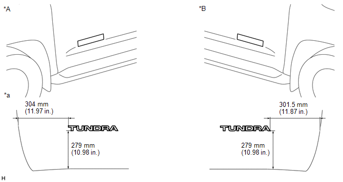 Text in Illustration Text in Illustration
3. INSTALL ROOF SIDE NO. 1 MARK LH HINT:
Standard:
NOTICE: Do not heat the vehicle body or roof side No. 1 mark LH excessively. (a) Clean the vehicle body surface. (1) Using a heat light, heat the vehicle body surface. (2) Remove the double-sided tape from the vehicle body. (3) Wipe off any tape adhesive residue with cleaner. (b) for Double Cab: (1) Install a new roof side No. 1 mark LH. (2) Using a heat light, heat the vehicle body and a new roof side No. 1 mark LH. (3) Remove the peeling paper from the face of the roof side No. 1 mark LH. HINT: After removing the peeling paper, keep the exposed adhesive free from foreign matter. (4) Install the roof side No. 1 mark LH in the position shown in the illustration. HINT: press the roof side No. 1 mark LH firmly to install it. 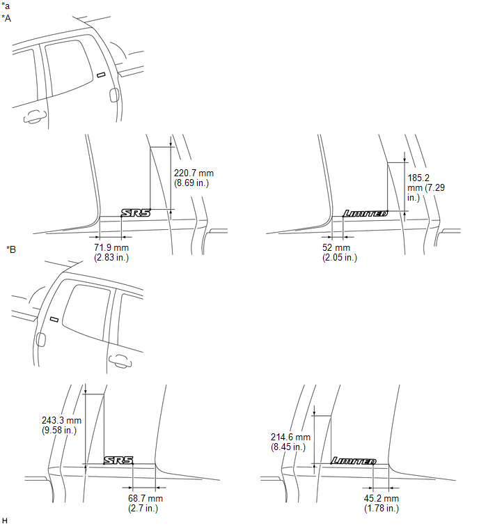 Text in Illustration Text in Illustration
(c) for CrewMax: (1) Install a new roof side No. 1 mark LH. (2) Using a heat light, heat the vehicle body and a new roof side No. 1 mark LH. (3) Remove the peeling paper from the face of the roof side No. 1 mark LH. HINT: After removing the peeling paper, keep the exposed adhesive free from foreign matter. (4) Install the roof side No. 1 mark LH in the position shown in the illustration. HINT: Press the roof side No. 1 mark LH firmly to install it. 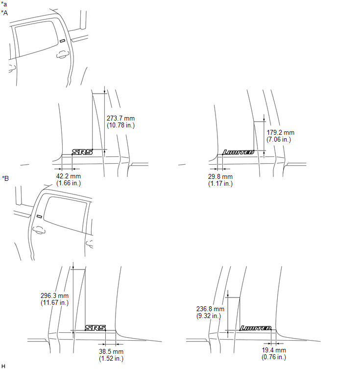 Text in Illustration Text in Illustration
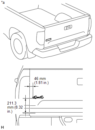
4. INSTALL REAR BODY NO. 3 NAME PLATE (for 4WD) HINT: When installing the rear body No. 3 name plate, heat the vehicle body and rear body No. 3 name plate using a heat light. Standard:
NOTICE: Do not heat the vehicle body or rear body No. 3 name plate excessively. (a) Clean the vehicle body surface. (1) Using a heat light, heat the vehicle body surface. (2) Remove the double-sided tape from the vehicle body. (3) Wipe off any tape adhesive residue with cleaner. (b) Install a new rear body No. 3 name plate.
(2) Remove the peeling paper from the face of the rear body No. 3 name plate. HINT: After removing the peeling paper, keep the exposed adhesive free from foreign matter. (3) Install the rear body No. 3 name plate in the position shown in the illustration. HINT: Press the rear body No. 3 name plate firmly to install it. Text in Illustration
5. INSTALL REAR BODY STRIPE LH HINT:
Standard:
NOTICE: Do not heat the vehicle body or rear body stripe LH excessively. (a) Clean the vehicle body surface. (1) Using a heat light, heat the vehicle body surface. (2) Remove the double-sided tape from the vehicle body. (3) Wipe off any tape adhesive residue with cleaner. (b) Installation temperature (1) When the ambient temperature is below 15°C (59°F), perform the installation procedure after warming the vehicle body surface (installation surface of the door frame, etc.) and tape to between 20 and 30°C (68 and 86°F) using a heat light. When the ambient temperature is higher than 35°C (95°F), cool the vehicle body surface (installation surface of the door frame, etc.) and tape to between 20 and 30°C (68 and 86°F) prior to installation. HINT:
(c) Before installation (1) Make sure any dirt on and around the vehicle body surface where the tape will be installed (installation surface of the door frame, etc.) is removed, and that the surface is smooth. If the surface is rough or dirt remains when pressing the tape onto the surface, air will be trapped under the tape and result in a poor appearance. HINT: Spray water on the shop floor to settle any dust. (d) Key points for handling the tape (1) The tape bends and rolls up easily. Store the tape between flat pieces of cardboard or other similar objects and keep it dry and level. NOTICE: Do not bend the tape or leave it in a place with a high temperature. (e) Key points for the installation of the tape (how to use a squeegee and the installation procedure for a flat surface). NOTICE:
(1) To avoid air bubbles, slightly raise the part of the tape that is going to be applied so that its adhesive surface does not touch the vehicle body while applying the tape. Tilt the squeegee 40 to 50° (for pressing forward) or 30 to 45° (for pulling) from the vehicle body surface and press with a force of 20 to 30 N (2 to 3 kgf) while moving the squeegee at a constant slow speed of 3 to 7 cm (1.2 to 2.8 in.) per second. 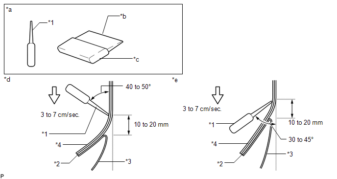
NOTICE: Be sure to observe the specified pressing speed, force and angle of the squeegee to avoid wrinkles and air bubbles. HINT:
(f) Key points for the installation of the tape (how to use a squeegee and the installation procedure for corners) (1) Remove the release paper and apply the tape carefully with your fingers. (2) Before applying the tape to each corner, heat the tape using a heat light and gradually apply it to avoid wrinkles in the tape and achieve a neat finish. (g) Check after installation (1) After completing the application, check if the tape is applied neatly. If the tape is not applied neatly, apply new tape. NOTICE: Do not reuse the tape. (h) Install a new rear body stripe LH. (1) Using a heat light, heat the vehicle body and a new rear body stripe LH. (2) Remove the peeling paper from the face of the rear body stripe LH. (3) Align the application tape with the rear end character line and using a squeegee, apply the rear body stripe LH. (4) Remove the application sheet. 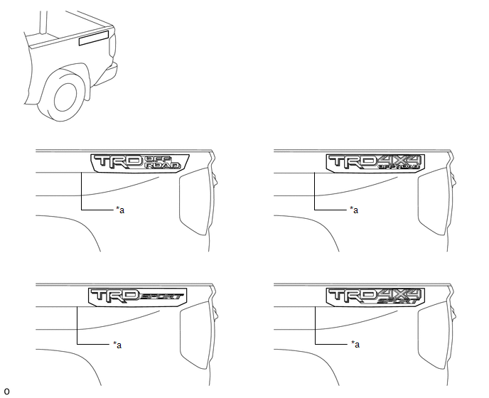
|
Toyota Tundra Service Manual > Back Window Glass(for Crewmax): Components
COMPONENTS ILLUSTRATION ILLUSTRATION ILLUSTRATION ILLUSTRATION ILLUSTRATION ILLUSTRATION ...