DESCRIPTION The stereo component tuner assembly sends the sound data signal or image data signal from a device to the radio and display receiver assembly via this circuit. WIRING DIAGRAM 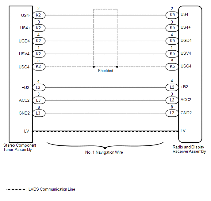 PROCEDURE
(a) Disconnect the K5 and L2 radio and display receiver assembly connectors. (b) Disconnect the K2 and L3 stereo component tuner assembly connectors. (c) Measure the resistance according to the value(s) in the table below. Standard Resistance:
(a) Replace the No. 1 navigation wire with a known good one.
(b) Check that the malfunction disappears. OK.: Malfunction disappears
|
Toyota Tundra Service Manual > Rear View Monitor System(for Navigation Receiver Type): Image from Camera for Rear View Monitor is Abnormal
DESCRIPTION This is the display signal circuit between the navigation receiver assembly and the television camera assembly. WIRING DIAGRAM PROCEDURE 1. CHECK HARNESS AND CONNECTOR (NAVIGATION RECEIVER ASSEMBLY - TELEVISION CAMERA ASSEMBLY) NG REPAIR OR REPLACE HARNESS OR CONNECTOR OK 2. CHECK NAVIGA ...


