DISASSEMBLY PROCEDURE 1. REMOVE LICENSE PLATE LIGHT ASSEMBLY LH
2. REMOVE LICENSE PLATE LIGHT ASSEMBLY RH HINT: Use the same procedure described for the LH side. 3. REMOVE REAR BUMPER PLATE LH
4. REMOVE REAR BUMPER PLATE RH HINT: Use the same procedure described for the LH side. 5. REMOVE REAR BUMPER PAD SUB-ASSEMBLY LH
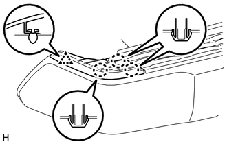
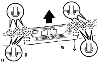
(b) Detach the 12 claws and 2 guides and remove the rear bumper pad sub-assembly LH as shown in the illustration. (c) Detach the clamp from the No. 2 frame wire. 6. REMOVE REAR BUMPER EXTENSION INSERT LH
7. REMOVE REAR BUMPER EXTENSION INSERT RH HINT: Use the same procedure described for the LH side. 8. REMOVE REAR BUMPER BAR CORNER REINFORCEMENT LH
9. REMOVE REAR BUMPER BAR CORNER REINFORCEMENT RH HINT: Use the same procedure described for the LH side. 10. REMOVE BLIND SPOT MONITOR SENSOR LH (w/ Blind Spot Monitor System)
11. REMOVE BLIND SPOT MONITOR SENSOR RH (w/ Blind Spot Monitor System) HINT: Use the same procedure described for the LH side. 12. REMOVE NO. 2 ULTRASONIC SENSOR (w/ Intuitive Parking Assist System)
13. REMOVE NO. 3 ULTRASONIC SENSOR (w/ Intuitive Parking Assist System)
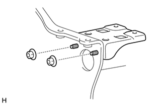
14. REMOVE NO. 2 FRAME WIRE (a) w/ Towing Package: (1) Detach all the clamps and remove the No. 2 frame wire from the receiver hitch bracket sub-assembly. 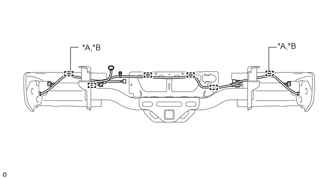
(b) w/o Towing Package: (1) Detach all the clamps and remove the No. 2 frame wire from the rear bumper reinforcement sub-assembly. 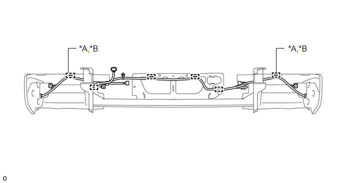
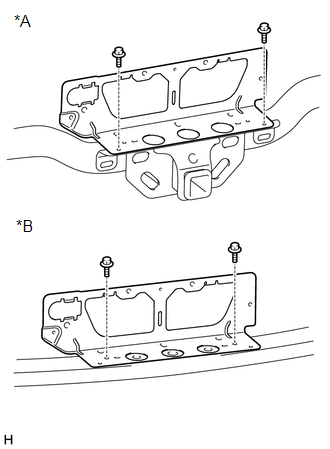
15. REMOVE REAR BUMPER SIDE STAY LH
16. REMOVE REAR BUMPER SIDE STAY RH HINT: Use the same procedure described for the LH side. 17. REMOVE REAR BUMPER PLATE
18. REMOVE REAR BUMPER UPPER COVER LH
19. REMOVE REAR BUMPER UPPER COVER RH HINT: Use the same procedure described for the LH side. |
Toyota Tundra Service Manual > Exterior: Tail Gate Protector
Components COMPONENTS ILLUSTRATION Installation INSTALLATION PROCEDURE 1. INSTALL TAIL GATE PROTECTOR (a) Attach the 16 clips to install the tail gate protector. (b) Install the 4 clips. Removal REMOVAL PROCEDURE 1. REMOVE TAIL GATE PROTECTOR (a) Put protective tape around the tail gate protector. ( ...