INSTALLATION CAUTION / NOTICE / HINT HINT:
Standard heating temperature:
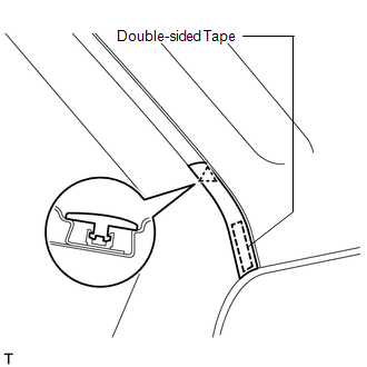
NOTICE: Do not heat the vehicle body, moulding and clip excessively. PROCEDURE 1. INSTALL ROOF DRIP SIDE FINISH MOULDING CLIP HINT: Perform this procedure only when installing new clips. (a) Using a heat light, heat the clip installation areas on the vehicle body. (b) Remove the double-sided tape from the vehicle body. (c) Wipe off any tape adhesive residue with cleaner. (d) Using a heat light, heat the clips. (e) Remove the peeling paper from the face of the clips. HINT: After removing the peeling paper, keep the exposed adhesive free from foreign matter. (f) Install the clips in the positions shown in the illustration. HINT: Press the clips firmly to install them. 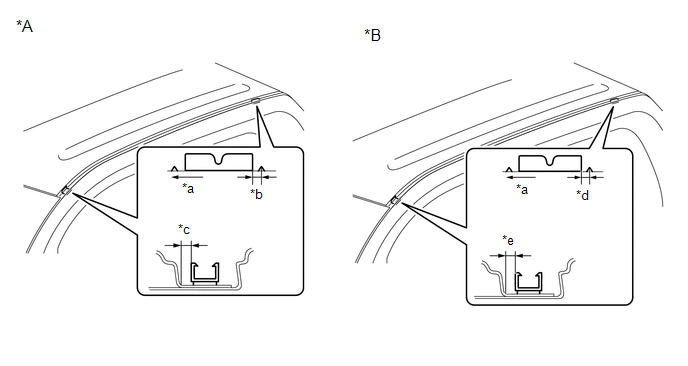
2. INSTALL ROOF DRIP SIDE FINISH MOULDING LH (a) Attach the clip to install the moulding. 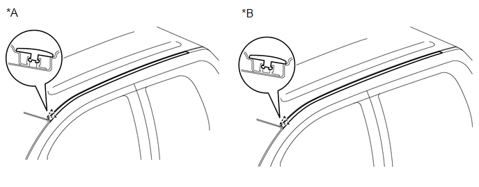
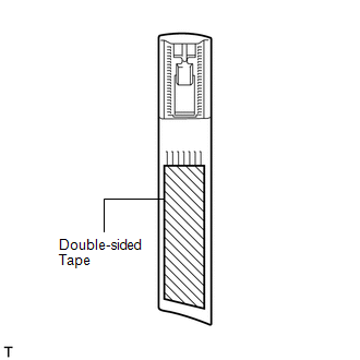
3. INSTALL REAR ROOF DRIP SIDE FINISH MOULDING LH (a) Clean the vehicle body surface. (1) Using a heat light, heat the vehicle body surface. (2) Remove the double-sided tape from the vehicle body. (3) Wipe off any tape adhesive residue with cleaner. (b) If reusing the moulding: Clean the moulding. (1) Using a heat light, heat the moulding. (2) Remove the double-sided tape from the moulding. (3) Wipe off any tape adhesive residue with cleaner.
(c) Install the moulding. (1) Using a heat light, heat the vehicle body and moulding. (2) Remove the peeling paper from the face of the moulding. HINT: After removing the peeling paper, keep the exposed adhesive free from foreign matter.
|
Toyota Tundra Service Manual > Condenser: Components
COMPONENTS ILLUSTRATION *1 AIR CONDITIONER TUBE ASSEMBLY *2 COOLER CONDENSER ASSEMBLY *3 COOLER DRYER *4 NO. 1 COOLER REFRIGERANT DISCHARGE HOSE *5 CAP *6 O-RING N*m (kgf*cm, ft.*lbf): Specified torque ● Non-reusable part Compressor oil ND-OIL 12 or equivalent - - ...