REMOVAL CAUTION / NOTICE / HINT HINT:
PROCEDURE 1. REMOVE LOWER NO. 1 SIDE PANEL MOULDING LH HINT: When removing the lower No. 1 side panel moulding LH, heat the vehicle body and lower No. 1 side panel moulding LH using a heat light. Standard:
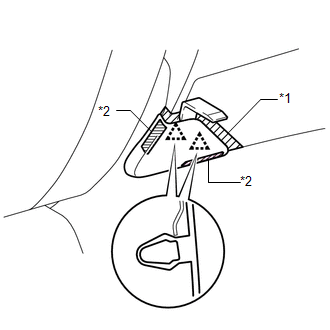
NOTICE: Do not heat the vehicle body and lower No. 1 side panel moulding LH excessively. (a) for Double Cab: (1) Using a heat light, heat the vehicle body and lower No. 1 side panel moulding LH. (2) Put protective tape around the lower No. 1 side panel moulding LH.
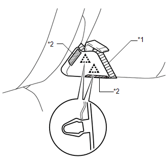
(b) for CrewMax: (1) Using a heat light, heat the vehicle body and lower No. 1 side panel moulding LH. (2) Put protective tape around the lower No. 1 side panel moulding LH.
2. REMOVE REAR BODY NO. 3 PROTECTOR LH HINT: When removing the rear body No. 3 protector LH, heat the vehicle body and rear body No. 3 protector LH using a heat light. Standard:
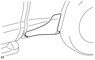
NOTICE: Do not heat the vehicle body or rear body No. 3 protector LH excessively. (a) for Double Cab: (1) Using a heat light, heat the vehicle body and rear body No. 3 protector LH.
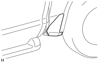
(b) for CrewMax: (1) Using a heat light, heat the vehicle body and rear body No. 3 protector LH.
|
Toyota Tundra Service Manual > Front Drive Shaft Assembly(for 4wd): Disassembly
DISASSEMBLY PROCEDURE 1. REMOVE INBOARD JOINT BOOT CLAMP (a) Using a side cutter, cut the 2 inboard joint boot clamps and remove them. 2. DISCONNECT INBOARD JOINT BOOT (a) Disconnect the inboard joint boot from the inboard joint shaft. 3. REMOVE INBOARD JOINT SHAFT (a) Place matchmarks on the inboar ...