Parts Location PARTS LOCATION ILLUSTRATION 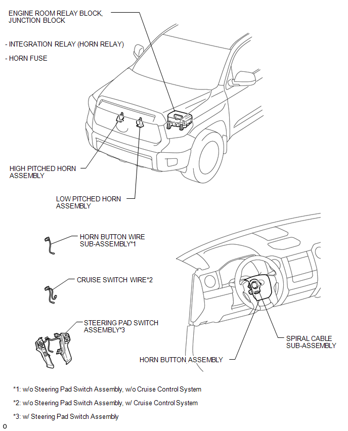
Problem Symptoms Table PROBLEM SYMPTOMS TABLE HINT: Use the table below to help determine the cause of the problem symptom. The potential causes of the symptoms are listed in order of probability in the "Suspected Area" column of the table. Check each symptom by checking the suspected areas in the order they are listed. Replace parts as necessary. Horn system
System Diagram SYSTEM DIAGRAM 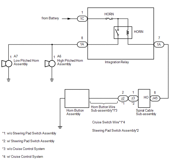 |
Toyota Tundra Service Manual > Differential Carrier Assembly(for 3ur-fe, 3ur-fbe): Installation
INSTALLATION PROCEDURE 1. INSTALL REAR DIFFERENTIAL CARRIER ASSEMBLY (a) Clean the contact surfaces of the rear differential carrier and rear axle housing. (b) Install a new gasket and the differential carrier with the 10 washers and 10 nuts. Torque: 72 N·m {734 kgf·cm, 53 ft·lbf} NOTICE: Be care ...


