DISASSEMBLY PROCEDURE 1. REMOVE BOX BOTTOM MAT 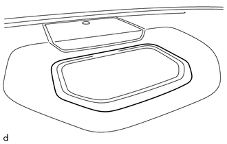
(a) Remove the box bottom mat. 2. REMOVE NO. 1 SPEAKER HOLE COVER (a) Apply protective tape as shown in the illustration. 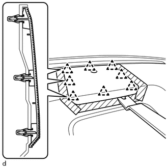
(b) Using a moulding remover B, detach the 8 clips and remove the No. 1 speaker hole cover. (c) Disconnect the connector. 3. REMOVE FRONT NO. 4 SPEAKER ASSEMBLY (w/ Front Center Speaker) Click here 4. REMOVE NO. 1 INSTRUMENT PANEL PIN HINT: Use the same procedure to remove the No. 1 instrument panel pin on the other side.
5. REMOVE DEFROSTER NOZZLE ASSEMBLY 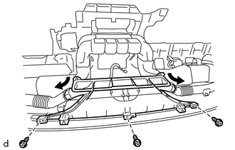
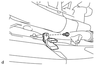
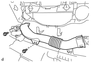
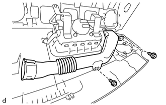
(a) Disconnect the No. 1 side defroster nozzle duct and No. 2 side defroster nozzle duct from the defroster nozzle assembly. (b) Remove the 3 screws <E> and defroster nozzle assembly. 6. REMOVE NO. 2 HEATER TO REGISTER DUCT (a) Remove the 8 screws <E> and No. 2 heater to register duct. 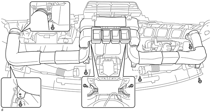
7. REMOVE NO. 1 SIDE DEFROSTER NOZZLE DUCT
8. REMOVE NO. 2 SIDE DEFROSTER NOZZLE DUCT
9. REMOVE INSTRUMENT CLUSTER FINISH PANEL REINFORCEMENT 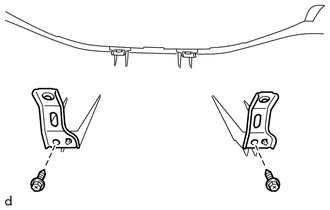
(a) Remove the 2 screws <F> and 2 instrument cluster finish panel reinforcements. 10. REMOVE NAVIGATION ANTENNA ASSEMBLY (w/ Navigation System) Click here 11. REMOVE FRONT PASSENGER AIRBAG ASSEMBLY Click here |
Toyota Tundra Service Manual > Cruise Control System: Fail-safe Chart
FAIL-SAFE CHART HINT: If any of the following conditions are detected while the cruise control system is controlling vehicle speed, the system clears the vehicle speed stored in the ECM and cancels control of vehicle speed by the cruise control system. Auto Cancel Condition Warning Fail-safe Deactiv ...