REMOVAL PROCEDURE 1. PRECAUTION NOTICE: After turning the ignition switch off, waiting time may be required before disconnecting the cable from the battery terminal. Therefore, make sure to read the disconnecting the cable from the battery terminal notice before proceeding with work. Click here 2. DISCONNECT CABLE FROM NEGATIVE BATTERY TERMINAL CAUTION: Wait at least 90 seconds after disconnecting the cable from the negative (-) battery terminal to disable the SRS system. NOTICE: When disconnecting the cable, some systems need to be initialized after the cable is reconnected. Click here 3. REMOVE FRONT SEAT ASSEMBLY (for Manual Seat) Click here 4. REMOVE FRONT SEAT ASSEMBLY (for Power Seat) Click here 5. REMOVE FRONT SEAT ASSEMBLY (for Center Seat) Click here 6. REMOVE REAR SEAT ASSEMBLY Click here 7. REMOVE FRONT DOOR SCUFF PLATE LH 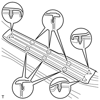
(a) Detach the 6 claws and 3 clips, and remove the front door scuff plate LH. 8. REMOVE FRONT DOOR SCUFF PLATE RH HINT: Use the same procedure described for the LH side. 9. REMOVE REAR DOOR SCUFF PLATE LH 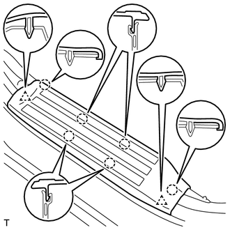
(a) Detach the 6 claws and 2 clips, and remove the rear door scuff plate LH. 10. REMOVE REAR DOOR SCUFF PLATE RH HINT: Use the same procedure described for the LH side. 11. REMOVE COWL SIDE TRIM BOARD LH 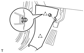
(a) Remove the nut. (b) Detach the 2 clips and remove the cowl side trim board LH. 12. REMOVE COWL SIDE TRIM BOARD RH HINT: Use the same procedure described for the LH side. 13. REMOVE FRONT DOOR OPENING TRIM WEATHERSTRIP LH (a) Remove the front door opening trim weatherstrip LH. 14. REMOVE FRONT DOOR OPENING TRIM WEATHERSTRIP RH HINT: Use the same procedure described for the LH side. 15. REMOVE REAR DOOR OPENING TRIM WEATHERSTRIP LH (a) Remove the rear door opening trim weatherstrip LH. 16. REMOVE REAR DOOR OPENING TRIM WEATHERSTRIP RH HINT: Use the same procedure described for the LH side. 17. REMOVE FRONT PILLAR GARNISH LH (a) Apply protective tape as shown in the illustration. 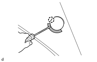
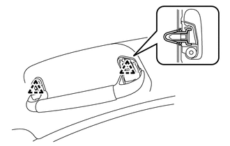
(b) Using a screwdriver, detach the claw and open the cover. HINT: Tape the screwdriver tip before use.
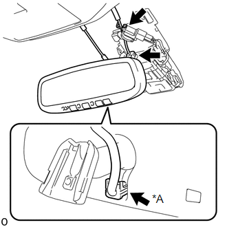
(d) Detach the clip and remove the front pillar garnish LH. (e) Protect the curtain shield airbag assembly. (1) Completely cover the curtain shield airbag assembly with a cloth or nylon sheet and secure the ends of the cover with adhesive tape as shown in the illustration. NOTICE: Cover the curtain shield airbag assembly with a protective cover as soon as the front pillar garnish LH is removed. 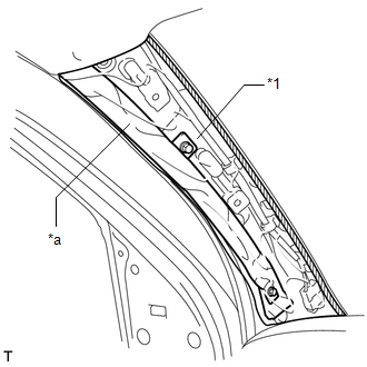
18. REMOVE FRONT PILLAR GARNISH RH (a) Apply protective tape as shown in the illustration. 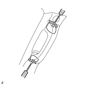
(b) Using a screwdriver, detach the 2 claws and open the 2 assist grip covers. HINT: Tape the screwdriver tip before use.
(e) Protect the curtain shield airbag assembly. (1) Completely cover the curtain shield airbag assembly with a cloth or nylon sheet and secure the ends of the cover with adhesive tape. NOTICE: Cover the curtain shield airbag assembly with a protective cover as soon as the front pillar garnish RH is removed. 19. REMOVE LOWER CENTER PILLAR GARNISH LH 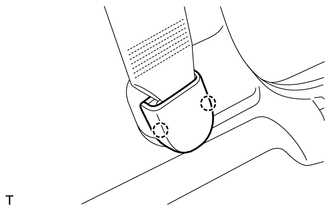
(a) Detach the 2 claws and remove the cover.
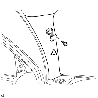
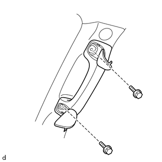
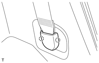
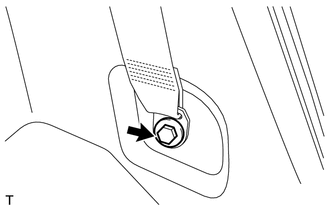
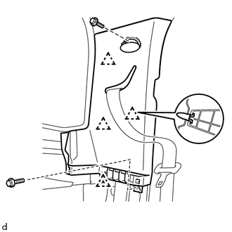
20. REMOVE LOWER CENTER PILLAR GARNISH RH HINT: Use the same procedure described for the LH side. 21. REMOVE CENTER PILLAR GARNISH LH (a) Using a screwdriver, detach the 2 claws and open the 2 assist grip covers. HINT: Tape the screwdriver tip before use. (b) Remove the 2 bolts and rear assist grip assembly from the center pillar garnish LH. (c) Remove the bolt. (d) Detach the clip, guide and remove the center pillar garnish LH. 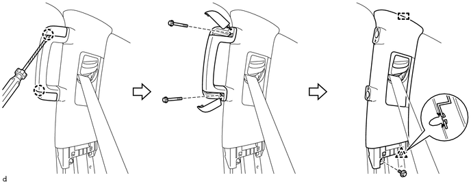
(e) Pass the front seat outer belt assembly LH through the hole of the center pillar garnish LH. 22. REMOVE CENTER PILLAR GARNISH RH HINT: Use the same procedure described for the LH side. 23. REMOVE FRONT SHOULDER BELT ANCHOR PLATE SUB-ASSEMBLY LH 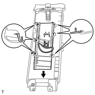
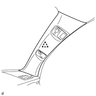
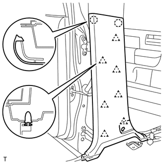
(a) Detach the 6 claws of the front shoulder belt anchor plate sub-assembly LH, and slide the front shoulder belt anchor plate sub-assembly LH in the direction of the arrow to remove it. 24. REMOVE FRONT SHOULDER BELT ANCHOR PLATE SUB-ASSEMBLY RH HINT: Use the same procedure described for the LH side. 25. REMOVE LOWER QUARTER TRIM PANEL ASSEMBLY LH
26. REMOVE LOWER QUARTER TRIM PANEL ASSEMBLY RH HINT: Use the same procedure described for the LH side. 27. REMOVE FRONT QUARTER TRIM PANEL ASSEMBLY LH (a) Apply protective tape as shown in the illustration. 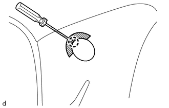
(b) Using a screwdriver, detach the claw and open the cover. HINT: Tape the screwdriver tip before use.
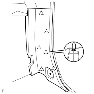
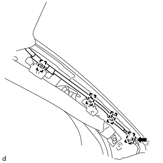
(d) Detach the 4 clips and remove the front quarter trim panel assembly LH. (e) Pass the rear seat outer belt assembly through the hole of the front quarter trim panel assembly LH. 28. REMOVE FRONT QUARTER TRIM PANEL ASSEMBLY RH HINT: Use the same procedure described for the LH side. 29. REMOVE ROOF CONSOLE BOX ASSEMBLY Click here 30. REMOVE INNER REAR VIEW MIRROR STAY HOLDER COVER (w/ EC Mirror) Click here 31. REMOVE NO. 1 ROOM LIGHT ASSEMBLY Click here 32. REMOVE VISOR ASSEMBLY LH 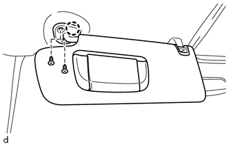
(a) Remove the 2 screws. (b) Detach the claw and remove the visor assembly LH.
33. REMOVE VISOR ASSEMBLY RH HINT: Use the same procedure described for the LH side. 34. REMOVE VISOR HOLDER HINT: Use the same procedure to remove the visor holder on the other side.
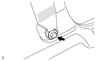
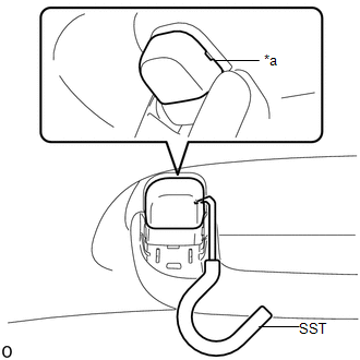
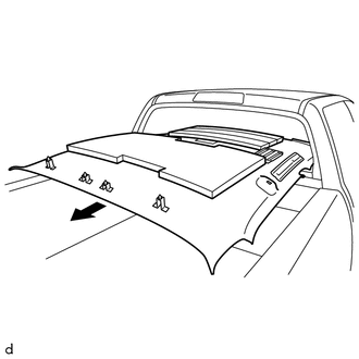
35. REMOVE BACK WINDOW ASSEMBLY (a) for Fixed Type: Click here (b) for Slide Type: Click here (c) for Power Slide Type: Click here 36. REMOVE ASSIST GRIP SUB-ASSEMBLY HINT: Use the same procedure for all the assist grip sub-assemblies.
(b) Pull SST as shown in the illustration to disengage the claw. NOTICE: To prevent the assist grip assembly from being damaged, make sure to only pull SST as shown in the illustration. HINT: Use the same procedure for the claw on the other side of the assist grip cover LH. 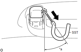
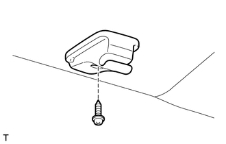
37. REMOVE COAT HOOK HINT: Use the same procedure to remove the coat hook on the other side. (a) Using a screwdriver, detach the 2 claws and remove the coat hook cap. 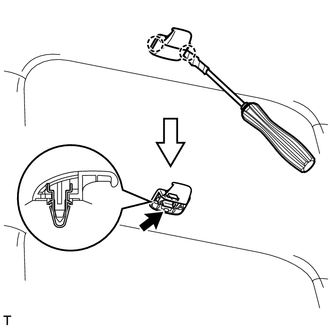
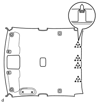
HINT: Tape the screwdriver tip before use. (b) Detach the clip and remove the coat hook. 38. REMOVE NO. 1 FORWARD RECOGNITION COVER (w/ Lane Departure Alert System) Click here 39. REMOVE ROOF HEADLINING ASSEMBLY (a) w/ Lane Departure Alert System:
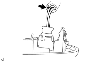
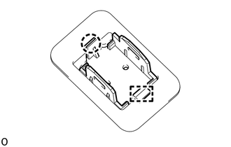
40. REMOVE TELEPHONE MICROPHONE ASSEMBLY Click here 41. REMOVE MICROPHONE CASE
(b) Detach the guide and remove the microphone case. |
Toyota Tundra Service Manual > Sliding Roof System: How To Proceed With Troubleshooting
CAUTION / NOTICE / HINT HINT: Use these procedures to troubleshoot the sliding roof system. *: Use the Techstream. PROCEDURE 1. VEHICLE BROUGHT TO WORKSHOP NEXT 2. INSPECT BATTERY VOLTAGE Standard voltage: 11 to 14 V If the voltage is below 11 V, recharge or replace the battery before proceeding. NE ...