Toyota Tundra Service Manual: Inspection

INSPECTION

PROCEDURE

1. INSPECT HEADLIGHT DIMMER SWITCH ASSEMBLY

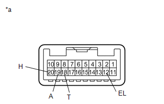
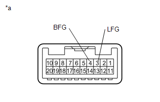
(a) Inspect the light control switch.

(1) Measure the resistance according to the value(s) in the table below.

Standard Resistance:

Tester Connection

Switch Condition

Specified Condition

20 (H) - 12 (EL)

Light control switch off or DRL OFF

10 kΩ or higher

18 (T) - 12 (EL)

19 (A) - 12 (EL)

18 (T) - 12 (EL)

Light control switch tail

Below 1 Ω

18 (T) - 12 (EL)

Light control switch head

Below 1 Ω

20 (H) - 12 (EL)

19 (A) - 12 (EL)

Light control switch auto

Below 1 Ω

If the result is not as specified, replace the headlight dimmer switch assembly.

Text in Illustration

*a

Component without harness connected

(Headlight Dimmer Switch Assembly)

(b) Inspect the headlight dimmer switch.

(1) Measure the resistance according to the value(s) in the table below.

HINT:

Perform the flash, high beam and low beam inspections with the light control switch on head.

Standard Resistance:

Tester Connection

Switch Condition

Specified Condition

11 (HU) - 12 (EL)

Headlight dimmer switch flash

Below 1 Ω

17 (HF) - 12 (EL)

11 (HU) - 12 (EL)

Headlight dimmer switch hi beam

Below 1 Ω

16 (HL) - 12 (EL)

Headlight dimmer switch low beam

Below 1 Ω

If the result is not as specified, replace the headlight dimmer switch assembly.

Text in Illustration

*a

Component without harness connected

(Headlight Dimmer Switch Assembly)

(c) Inspect the turn signal switch.

(1) Measure the resistance according to the value(s) in the table below.

Standard Resistance:

Tester Connection

Switch Condition

Specified Condition

13 (TR) - 12 (EL)

15 (TL) - 12 (EL)

14 (CR) - 12 (EL)

Turn signal switch neutral

10 kΩ or higher

13 (TR) - 12 (EL)

Turn signal switch right turn

Below 1 Ω

13 (TR) - 12 (EL)

11 (TL) - 14 (CR)

14 (CR) - 12 (EL)

Turn signal switch right lane change

Below 1 Ω

15 (TL) - 12 (E)

Turn signal switch left turn

Below 1 Ω

15 (TL) - 12 (EL)

15 (TL) - 14 (CR)

14 (CR) - 12 (EL)

Turn signal switch left lane change

Below 1 Ω

If the result is not as specified, replace the headlight dimmer switch assembly.

Text in Illustration

*a

Component without harness connected

(Headlight Dimmer Switch Assembly)

(d) Inspect the front fog light switch.

(1) Measure the resistance according to the value(s) in the table below.

Standard Resistance:

Tester Connection

Switch Condition

Specified Condition

3 (LFG) - 4 (BFG)

Front fog light switch off

10 kΩ or higher

3 (LFG) - 4 (BFG)

Front fog light switch on

Below 1 Ω

If the result is not as specified, replace the headlight dimmer switch assembly.

Text in Illustration

*a

Component without harness connected

(Headlight Dimmer Switch Assembly)

    Components

    Installation

    See More:

    Toyota Tundra Service Manual > Rear Door Lock(for Crewmax): Installation
    INSTALLATION PROCEDURE 1. INSTALL REAR DOOR INSIDE LOCKING CABLE ASSEMBLY LH 2. INSTALL REAR DOOR LOCK REMOTE CONTROL CABLE ASSEMBLY LH 3. INSTALL REAR DOOR LOCK ASSEMBLY LH 4. INSTALL REAR DOOR GLASS SUB-ASSEMBLY LH 5. INSTALL REAR DOOR REAR LOWER WINDOW FRAME SUB-ASSEMBLY LH 6. INSTALL REAR DOOR G ...

    Toyota Tundra Owners Manual

    Toyota Tundra Service Manual

    © 2024 Copyright www.ttundra.com
    0.0282