Toyota Tundra Service Manual: ACC Signal Circuit

DESCRIPTION

This circuit detects the ignition switch ACC or off condition, and sends it to the main body ECU (multiplex network body ECU).

WIRING DIAGRAM

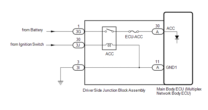
CAUTION / NOTICE / HINT

NOTICE:

Inspect the fuses for circuits related to this system before performing the following procedure.

PROCEDURE

1.

READ VALUE USING TECHSTREAM

(a) Read the Data List according to the display on the Techstream.

Click here

Main Body

Tester Display

Measurement Item / Range

Normal Condition

Diagnostic Note

ACC SW

Ignition switch signal / OFF or ON

OFF: Ignition switch off

ON: Ignition switch ACC

"ON" is also displayed for this item when the ignition switch is ON.

OK:

Normal conditions listed above are displayed.

OK

PROCEED TO NEXT SUSPECTED AREA SHOWN IN PROBLEM SYMPTOMS TABLE

NG

2.

CHECK HARNESS AND CONNECTOR (DRIVER SIDE JUNCTION BLOCK ASSEMBLY - BATTERY AND BODY GROUND)

(a) Disconnect the driver side junction block assembly connectors.

*a

Front view of wire harness connector

(to Driver Side Junction Block Assembly)

-

-

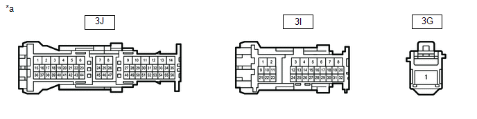
(b) Measure the voltage according to the value(s) in the table below.

Standard Voltage:

Tester Connection

Condition

Specified Condition

3G-1 - Body ground

Always

11 to 14 V

3J-30 - Body ground

Ignition switch ACC

11 to 14 V

Ignition switch off

Below 1 V

(c) Measure the resistance according to the value(s) in the table below.

Standard Resistance:

Tester Connection

Condition

Specified Condition

3I-3 - Body ground

Always

Below 1 Ω

NG

REPAIR OR REPLACE HARNESS OR CONNECTOR

OK

3.

CHECK DRIVER SIDE JUNCTION BLOCK ASSEMBLY

(a) Remove the driver side junction block assembly.

Click here

*a

Component without harness connected

(Driver Side Junction Block Assembly)

-

-

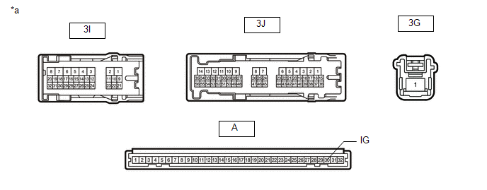
(b) Remove the main body ECU (multiplex network body ECU) from the driver side junction block assembly.

Click here

(c) Measure the resistance according to the value(s) in the table below.

Standard Resistance:

Tester Connection

Condition

Specified Condition

3G-1 - A-30 (ACC)

Battery not connected to 3J-30 and 3I-3

10 kΩ or higher

Battery positive (+) → 3J-30

Battery negative (-) → 3I-3

Below 1 Ω

OK

REPLACE MAIN BODY ECU (MULTIPLEX NETWORK BODY ECU)

NG

REPLACE DRIVER SIDE JUNCTION BLOCK ASSEMBLY

    Lighting System

    Automatic High Beam System does not Operate or Operation Indicator does not Illuminate

    See More:

    Toyota Tundra Service Manual > Can Communication System: Fail-safe Chart
    FAIL-SAFE CHART 1. FAIL-SAFE FUNCTION (a) When communication fails in any of the main wires (communication lines) due to a short circuit or other causes, the fail-safe function, which is specified for each system, operates to prevent the system from malfunctioning. (b) The table below shows the effe ...

    Toyota Tundra Owners Manual

    Toyota Tundra Service Manual

    © 2024 Copyright www.ttundra.com
    0.0322