DESCRIPTION This circuit is from the parking brake switch assembly to the radio and display receiver assembly. WIRING DIAGRAM 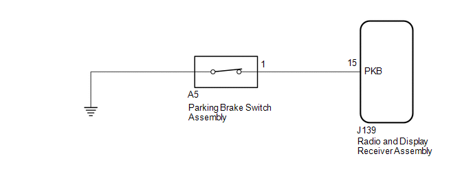 PROCEDURE
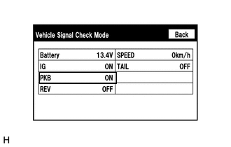
(b) Check that the display changes between ON and OFF according to the parking brake operation. OK:
HINT: This display is updated once per second. As a result, it is normal for the display to lag behind the actual parking brake operation.
(a) Disconnect the J139 radio and display receiver assembly connector. (b) Disconnect the A5 parking brake switch assembly connector. (c) Measure the resistance according to the value(s) in the table below. Standard Resistance:
(a) Remove the parking brake switch assembly (See page
(b) Inspect the parking brake switch assembly (See page
|
Toyota Tundra Service Manual > Fuel Pump: Installation
INSTALLATION CAUTION / NOTICE / HINT HINT: Perform "Inspection After Repairs" after replacing the fuel pump. Click here PROCEDURE 1. INSTALL FUEL SUCTION WITH PUMP AND GAUGE TUBE ASSEMBLY (a) Apply a light coat of gasoline to a new gasket, and install it to the fuel tank assembly. (b) Align the prot ...

 )]
)]