DESCRIPTION This circuit is the power source circuit for the combination meter assembly. This circuit provides 2 power source types: one is a constant power source mainly used as a backup power source, and other is a power source mainly used for signal transmission. The constant power source is mainly used as a backup power source of the meter CPU. However, it is also used for communication. If a voltage of 12 V is not applied to terminal IG+ when the ignition switch ON, the indicator will not operate. WIRING DIAGRAM 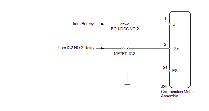
CAUTION / NOTICE / HINT NOTICE: Inspect the fuses for circuits related to this system before performing procedure. PROCEDURE
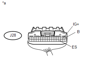
(a) Disconnect the J28 combination meter assembly connector. (b) Measure the resistance and voltage according to the value(s) in the table below. Standard Resistance:
Standard Voltage:
|
Toyota Tundra Service Manual > Can Communication System: System Diagram
SYSTEM DIAGRAM 1. SYSTEM DIAGRAM (a) The CAN communication system is composed of 7 buses. CAN Main Bus Line Terminating Resistor CAN Branch Line * Gateway Function Equipped ECU Bus Monitoring Direction - - Connected to Code ECU/Sensor Name CAN DTC Storage Note - CGW Central Gateway ECU (Network Gate ...


