Toyota Tundra Service Manual: Radio Receiver Power Source Circuit

DESCRIPTION

This circuit provides power to the radio and display receiver assembly.

WIRING DIAGRAM

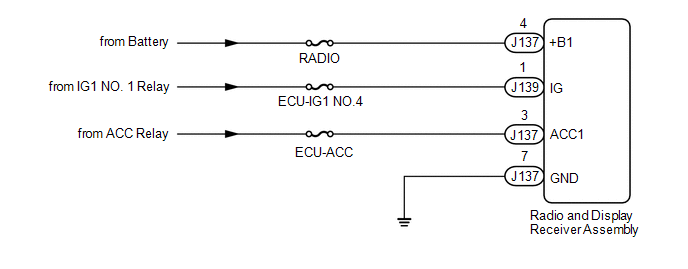
CAUTION / NOTICE / HINT

NOTICE:

Inspect the fuses for circuits related to this system before performing the following procedure.

PROCEDURE

1.

CHECK HARNESS AND CONNECTOR (RADIO AND DISPLAY RECEIVER ASSEMBLY - BATTERY AND GROUND)

(a) Disconnect the radio and display receiver assembly connector.

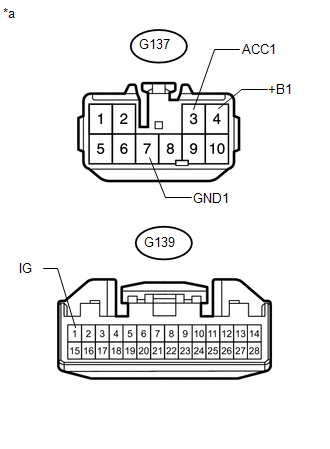
(b) Measure the resistance according to the value(s) in the table below.

Standard Resistance:

Tester Connection

Condition

Specified Condition

J137-7 (GND1) - Body ground

Always

Below 1 Ω

(c) Measure the voltage according to the value(s) in the table below.

Standard Voltage:

Tester Connection

Condition

Specified Condition

J137-4 (+B1) - Body ground

Always

11 to 14 V

J137-3 (ACC1) - Body ground

Ignition switch ACC

11 to 14 V

J139-1 (IG) - Body ground

Ignition switch ON

11 to 14 V

Text in Illustration

*a

Front view of wire harness connector

(to Radio and Display Receiver Assembly)

OK

PROCEED TO NEXT SUSPECTED AREA SHOWN IN PROBLEM SYMPTOMS TABLE

NG

REPAIR OR REPLACE HARNESS OR CONNECTOR

    Radio Broadcast cannot be Received (Bad Reception)

    Registered Device cannot be Deleted

    See More:

    Toyota Tundra Service Manual > Front Seat Cushion Heater(for Power Seat): Removal
    REMOVAL CAUTION / NOTICE / HINT CAUTION: Wear protective gloves. Sharp areas on the parts may injure your hands. HINT: Use the same procedure for the RH and LH sides. The procedure listed below is for the LH side. PROCEDURE 1. REMOVE FRONT SEAT ASSEMBLY (See page ) 2. REMOVE FRONT SEAT CUSHION SHIEL ...

    Toyota Tundra Owners Manual

    Toyota Tundra Service Manual

    © 2024 Copyright www.ttundra.com
    0.0101