Toyota Tundra Service Manual: Sound Signal Circuit between Radio Receiver and Stereo Jack Adapter

Toyota Tundra Service Manual / Audio, Visual, Telematics / Audio / Video / Audio And Visual System / Sound Signal Circuit between Radio Receiver and Stereo Jack Adapter

DESCRIPTION

The No. 1 stereo jack adapter assembly sends an external device sound signal to the radio and display receiver assembly through this circuit.

The sound signal that has been sent is amplified by the radio and display receiver assembly and then is sent to the speakers.

If there is an open or short in the circuit, sound cannot be heard from the speakers even if there is no malfunction in the radio and display receiver assembly or speakers.

WIRING DIAGRAM
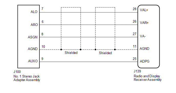
PROCEDURE

1.

CHECK HARNESS AND CONNECTOR (RADIO AND DISPLAY RECEIVER ASSEMBLY - NO. 1 STEREO JACK ADAPTER ASSEMBLY)

(a) Disconnect the J139 radio and display receiver assembly connector.

(b) Disconnect the J100 No. 1 stereo jack adapter assembly connector.

(c) Measure the resistance according to the value(s) in the table below.

Standard Resistance:

Tester Connection

Condition

Specified Condition

J139-28 (VAL+) - J100-7 (ALO)

Always

Below 1 Ω

J139-26 (VAR+) - J100-6 (ARO)

Always

Below 1 Ω

J139-27 (VA-) - J100-8 (ASGN)

Always

Below 1 Ω

J139-11 (AGND) - J100-10 (AGND)

Always

Below 1 Ω

J139-25 (ADPG) - J100-9 (AUXO)

Always

Below 1 Ω

J139-28 (VAL+) - Body ground

Always

10 kΩ or higher

J139-26 (VAR+) - Body ground

Always

10 kΩ or higher

J139-27 (VA-) - Body ground

Always

10 kΩ or higher

J139-11 (AGND) - Body ground

Always

10 kΩ or higher

J139-25 (ADPG) - Body ground

Always

10 kΩ or higher

OK

PROCEED TO NEXT SUSPECTED AREA SHOWN IN PROBLEM SYMPTOMS TABLE

NG

REPAIR OR REPLACE HARNESS OR CONNECTOR

    Sound Quality is Bad Only when Disc is Played (Volume is Too Low)

    Speaker Circuit

    See More:

    Toyota Tundra Service Manual > Main Body Ecu: Removal
    REMOVAL CAUTION / NOTICE / HINT NOTICE: Do not remove the main body ECU (multiplex network body ECU) except when replacing it. PROCEDURE 1. REMOVE LOWER NO. 1 INSTRUMENT PANEL AIRBAG ASSEMBLY Click here 2. REMOVE DRIVER SIDE JUNCTION BLOCK ASSEMBLY WITH MAIN BODY ECU (a) Remove the 2 nuts and discon ...

    Toyota Tundra Owners Manual

    Toyota Tundra Service Manual

    © 2025 Copyright www.ttundra.com
    0.0198