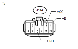
DESCRIPTION This circuit provides power to the stereo component amplifier assembly. WIRING DIAGRAM 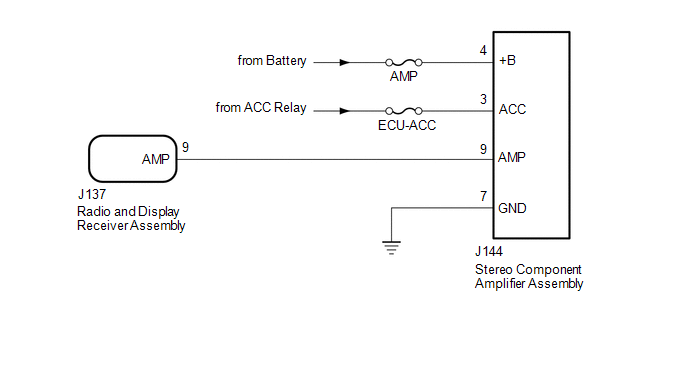 CAUTION / NOTICE / HINT NOTICE: Inspect the fuses for circuits related to this system before performing the following procedure. PROCEDURE
(b) Measure the resistance according to the value(s) in the table below. Standard Resistance:
(c) Measure the voltage according to the value(s) in the table below. Standard Voltage:
(a) Disconnect the J144 stereo component amplifier assembly connector. (b) Disconnect the J137 radio and display receiver assembly connector. (c) Measure the resistance according to the value(s) in the table below. Standard Resistance:
|
Toyota Tundra Service Manual > Valve Body Assembly: Disassembly
DISASSEMBLY PROCEDURE 1. REMOVE SHIFT SOLENOID VALVE SL2 (a) Remove the bolt, lock plate and 2 straight pins. (b) Remove the shift solenoid valve. 2. REMOVE SHIFT SOLENOID VALVE SLU 3. REMOVE SHIFT SOLENOID VALVE SLT (a) Remove the bolt, lock plate and 2 straight pins. (b) Remove the shift solenoid ...