Toyota Tundra Service Manual: Occupant Classification System Malfunction (B1650)

Toyota Tundra Service Manual / Vehicle Interior / Supplemental Restraint Systems / Airbag System / Occupant Classification System Malfunction (B1650)

DESCRIPTION

The occupant classification system circuit consists of the airbag sensor assembly and the occupant classification system.

If the airbag sensor assembly receives signals from the occupant classification ECU, it determines whether the front passenger airbag, the front seat airbag RH and front seat outer belt should be operated.

DTC B1650 is stored when a malfunction is detected in the occupant classification system circuit.
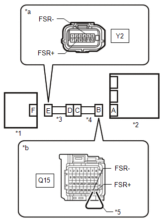
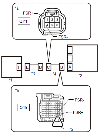
DTC No.

Detection Item

DTC Detection Condition

Trouble Area

Warning Indicate

Test Mode / Check Mode

B1650

Occupant Classification System Malfunction

When one of following conditions is met:

  • No. 2 Floor wire
  • Front seat wire RH
  • Occupant classification system
  • Airbag sensor assembly
  • No. 2 Floor wire
  • Front seat wire RH
  • Occupant classification system
  • Airbag sensor assembly

Comes on

Not applicable

WIRING DIAGRAM

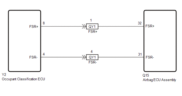
CAUTION / NOTICE / HINT

NOTICE:

  • After turning the ignition switch off, waiting time may be required before disconnecting the cable from the negative (-) battery terminal. Therefore, make sure to read the disconnecting the cable from the negative (-) battery terminal notices before proceeding with work.
  • When disconnecting the cable from the negative (-) battery terminal while performing repairs, some systems need to be initialized after the cable is reconnected.

PROCEDURE

1.

CHECK DTC (OCCUPANT CLASSIFICATION SYSTEM)

(a) Check for occupant classification system DTCs.

Click here

OK:

DTCs are not output.

NG

GO TO OCCUPANT CLASSIFICATION SYSTEM

OK

2.

CHECK CONNECTION OF CONNECTORS

(a) Turn the ignition switch off.

(b) Disconnect the cable from the negative (-) battery terminal, and wait for at least 90 seconds.

(c) Check that the connectors are properly connected to the airbag sensor assembly and occupant classification ECU.

OK:

The connectors are properly connected.

NG

CONNECT CONNECTORS PROPERLY

OK

3.

CHECK CONNECTORS

(a) Disconnect the connectors from the airbag sensor assembly and occupant classification ECU.

(b) Check that the connectors (on the airbag sensor assembly side and occupant classification ECU side) are not damaged.

OK:

The connectors are not deformed or damaged.

*1

Occupant Classification ECU

*2

Airbag Sensor Assembly

*3

Front Seat Wire RH

*4

No. 2 Floor Wire

NG

REPLACE FRONT SEAT WIRE RH OR NO. 2 FLOOR WIRE

OK

4.

CHECK OCCUPANT CLASSIFICATION ECU CIRCUIT

(a) Connect the cable to the negative (-) battery terminal, and wait for at least 2 seconds.

*1

Occupant Classification ECU

*2

Airbag Sensor Assembly

*3

Front Seat Wire RH

*4

No. 2 Floor Wire

*5

Service Wire

*a

Front view of wire harness connector

(to Occupant Classification ECU)

*b

Front view of wire harness connector

(to Airbag Sensor Assembly)

(b) Turn the ignition switch to ON.

(c) Measure the voltage according to the value(s) in the table below.

Standard Voltage:

Tester Connection

Switch Condition

Specified Condition

Y2-8 (FSR+) - Body ground

Ignition switch ON

Below 1 V

Y2-4 (FSR-) - Body ground

Ignition switch ON

Below 1 V

(d) Turn the ignition switch off.

(e) Disconnect the cable from the negative (-) battery terminal, and wait for at least 90 seconds.

(f) Using a service wire, connect terminals 32 (FSR+) and 31 (FSR-) of connector B.

NOTICE:

Do not forcibly insert the service wire into the terminals of the connector when connecting a service wire.

(g) Measure the resistance according to the value(s) in the table below.

Standard Resistance:

Tester Connection

Condition

Specified Condition

Y2-8 (FSR+) - Y2-4 (FSR-)

Always

Below 1 Ω

(h) Disconnect the service wire from connector B.

(i) Measure the resistance according to the value(s) in the table below.

Standard Resistance:

Tester Connection

Condition

Specified Condition

Y2-8 (FSR+) - Y2-4 (FSR-)

Always

1 MΩ or higher

Y2-8 (FSR+) - Body ground

Always

1 MΩ or higher

Y2-4 (FSR-) - Body ground

Always

1 MΩ or higher

NG

REPLACE AIRBAG SENSOR ASSEMBLY

OK

5.

CHECK NO. 2 FLOOR WIRE

(a) Disconnect the instrument panel wire connector from the engine room main wire.

*1

Occupant Classification ECU

*2

Airbag Sensor Assembly

*3

Front Seat Wire RH

*4

No. 2 Floor Wire

*5

Service Wire

*a

Front view of wire harness connector

(to Front Seat Wire RH)

*b

Front view of wire harness connector

(to Airbag Sensor Assembly)

(b) Connect the cable to the negative (-) battery terminal, and wait for at least 2 seconds.

(c) Turn the ignition switch to ON.

(d) Measure the voltage according to the value(s) in the table below.

Standard Voltage:

Tester Connection

Switch Condition

Specified Condition

QY1-1 (FSR+) - Body ground

Ignition switch ON

Below 1 V

QY1-4 (FSR-) - Body ground

Ignition switch ON

Below 1 V

(e) Turn the ignition switch off.

(f) Disconnect the cable from the negative (-) battery terminal, and wait for at least 90 seconds.

(g) Using a service wire, connect terminals 32 (FSR+) and 31 (FSR-) of connector B.

NOTICE:

Do not forcibly insert the service wire into the terminals of the connector when connecting a service wire.

(h) Measure the resistance according to the value(s) in the table below.

Standard Resistance:

Tester Connection

Condition

Specified Condition

QY1-1 (FSR+) - QY1-4 (FSR-)

Always

Below 1 Ω

(i) Disconnect the service wire from connector B.

(j) Measure the resistance according to the value(s) in the table below.

Standard Resistance:

Tester Connection

Condition

Specified Condition

QY1-1 (FSR+) - QY1-4 (FSR-)

Always

1 MΩ or higher

QY1-1 (FSR+) - Body ground

Always

1 MΩ or higher

QY1-4 (FSR-) - Body ground

Always

1 MΩ or higher

OK

REPLACE FRONT SEAT WIRE RH

NG

REPLACE FLOOR WIRE NO.2

    Curtain Shield Airbag Sensor Lost Communication (RH) (B1632,B1633,B1637,B1638)

    Seat Position Airbag Sensor Circuit Malfunction (B1653)

    See More:

    Toyota Tundra Service Manual > Center Airbag Sensor Assembly(for Floor Shift Type): Removal
    REMOVAL PROCEDURE 1. PRECAUTION CAUTION: Be sure to read precaution thoroughly before servicing. Click here NOTICE: After turning the ignition switch off, waiting time may be required before disconnecting the cable from the negative (-) battery terminal. Therefore, make sure to read the disconnectin ...

    Toyota Tundra Owners Manual

    Toyota Tundra Service Manual

    © 2024 Copyright www.ttundra.com
    0.012