REMOVAL PROCEDURE 1. REMOVE FRONT PILLAR GARNISH LH 2. REMOVE FRONT PILLAR GARNISH RH 3. REMOVE NO. 1 INSTRUMENT PANEL SPEAKER PANEL SUB-ASSEMBLY 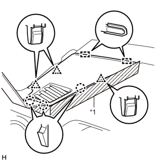 Text in Illustration Text in Illustration
(a) Apply protective tape as shown in the illustration. (b) Using moulding remover B, detach the 3 clips, 3 claws and 2 guides and remove the No. 1 instrument panel speaker panel sub-assembly. 4. REMOVE NO. 2 INSTRUMENT PANEL SPEAKER PANEL SUB-ASSEMBLY 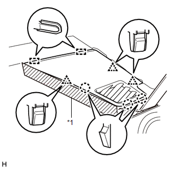 Text in Illustration Text in Illustration
(a) Apply protective tape as shown in the illustration. (b) Using moulding remover B, detach the 3 clips, 3 claws and 2 guides and remove the No. 2 instrument panel speaker panel sub-assembly. 5. REMOVE FRONT NO. 2 SPEAKER ASSEMBLY LH (a) Remove the 2 bolts. 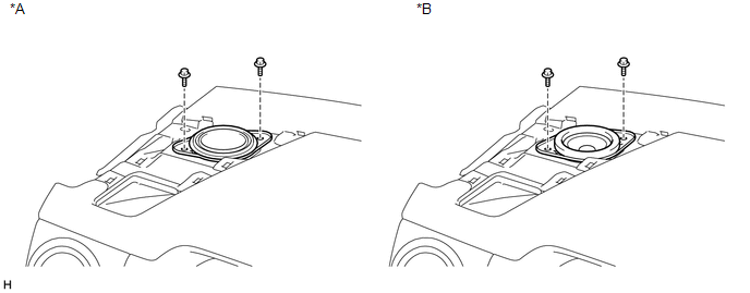 Text in Illustration Text in Illustration
(b) Disconnect the connector and remove the front No. 2 speaker assembly LH. NOTICE: Do not touch the cone part of the speaker. 6. REMOVE FRONT NO. 2 SPEAKER ASSEMBLY RH 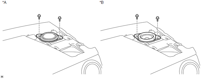 Text in Illustration Text in Illustration
(a) Remove the 2 bolts. (b) Disconnect the connector and remove the front No. 2 speaker assembly RH. NOTICE: Do not touch the cone part of the speaker. 7. REMOVE NO. 1 SPEAKER HOLE COVER 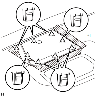 Text in Illustration Text in Illustration
(a) Apply protective tape as shown in the illustration. (b) Using moulding remover B, detach the 8 clips and remove the No. 1 speaker hole cover. 8. REMOVE FRONT NO. 4 SPEAKER ASSEMBLY (for 7 Speakers) 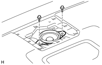 (a) Remove the 2 bolts. (b) Disconnect the connector and remove the front No. 4 speaker assembly. NOTICE: Do not touch the cone part of the speaker. |
Toyota Tundra Service Manual > Automatic Transmission System: Precaution
PRECAUTION NOTICE: When disconnecting the cable, some systems need to be initialized after the cable is reconnected (See page ). Perform Reset Memory procedures (A/T initialization) after replacing the automatic transmission assembly, valve body assembly or any of the shift solenoid valves (See page ...


