INSTALLATION PROCEDURE 1. INSTALL FENDER ANTENNA ASSEMBLY (a) Install the fender antenna assembly with the bolt. Torque: 9.0 N·m {92 kgf·cm, 80 in·lbf} (b) Attach the 5 clamps and install the bolt. Torque: 9.0 N·m {92 kgf·cm, 80 in·lbf} (c) Connect each connector. 2. INSTALL FRONT FENDER LINER RH 3. INSTALL SIDE STEP ASSEMBLY RH (w/ Side Step)
4. INSTALL FRONT FENDER MUDGUARD RH (w/ Front Fender Mudguard) 5. INSTALL ANTENNA ORNAMENT 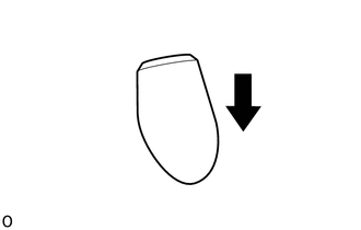 (a) Install the antenna ornament as shown in the illustration. 6. INSTALL INSTRUMENT PANEL SUB-ASSEMBLY (a) for Column Shift Type: (See page (b) for Floor Shift Type: (See page 7. CONNECT CABLE TO NEGATIVE BATTERY TERMINAL NOTICE: When disconnecting the cable, some systems need to be initialized after the cable is reconnected (See page
8. CHECK SRS WARNING LIGHT (See page 9. INSTALL PULL TOP ANTENNA POLE SUB-ASSEMBLY (See page
|
Toyota Tundra Service Manual > Cargo Light Switch: Removal
REMOVAL PROCEDURE 1. REMOVE FRONT DOOR SCUFF PLATE LH for Double Cab: (See page ) for CrewMax: (See page ) 2. REMOVE COWL SIDE TRIM BOARD LH 3. REMOVE INSTRUMENT SIDE PANEL LH 4. REMOVE LOWER INSTRUMENT PANEL FINISH PANEL SUB-ASSEMBLY LH 5. REMOVE DECK LIGHT SWITCH ASSEMBLY (a) Using a screwdriver, ...


