DESCRIPTION When the theft deterrent system is switched from the armed state to the alarm sounding state, the main body ECU (multiplex network body ECU) transmits a signal to cause the horn to sound at intervals of 0.4 seconds. WIRING DIAGRAM 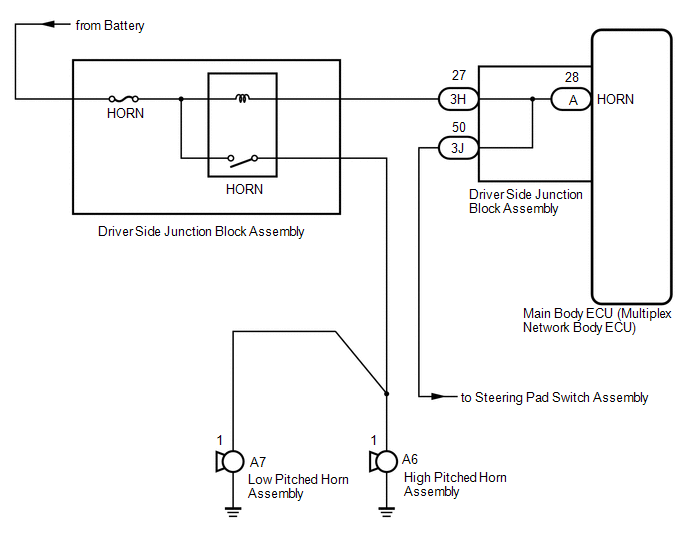
CAUTION / NOTICE / HINT NOTICE: Inspect the fuses for circuits related to this system before performing the following procedure. PROCEDURE
(a) Press the horn switch and check if the horns sound. Result
(a) Remove the driver side junction block assembly. Click here
|
Toyota Tundra Service Manual > Can Communication System: Check Bus 2 Line for Short to +B
DESCRIPTION There may be a short circuit between one of the CAN bus lines and +B when there is no resistance between terminal 18 (CA4H) of the central gateway ECU (network gateway ECU) and terminal 16 (BAT) of the DLC3, or terminal 17 (CA4L) of the central gateway ECU (network gateway ECU) and termi ...