Components COMPONENTS ILLUSTRATION 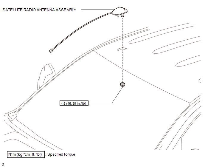 Installation INSTALLATION PROCEDURE 1. INSTALL SATELLITE RADIO ANTENNA ASSEMBLY (a) Attach the 2 claws and guide to install the satellite radio antenna assembly. (b) Install the nut. Torque: 4.5 N·m {45 kgf·cm, 39 in·lbf} 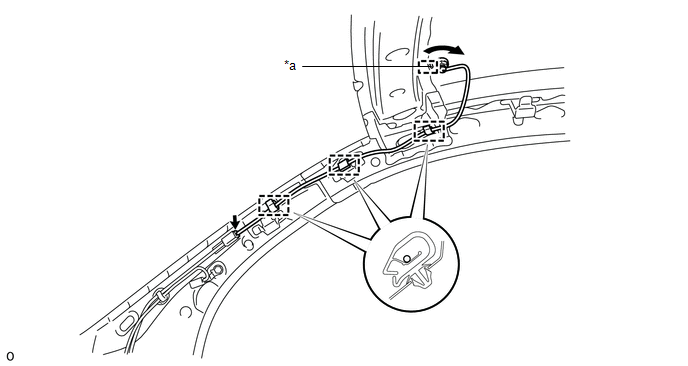 Text in Illustration Text in Illustration
(c) Attach the 3 clamps. (d) Connect the connector. 2. INSTALL ROOF HEADLINING ASSEMBLY (a) for Double Cab: Click here (b) for CrewMax: Click here
3. CONNECT CABLE TO NEGATIVE BATTERY TERMINAL NOTICE: When disconnecting the cable, some systems need to be initialized after the cable is reconnected. Click here Removal REMOVAL PROCEDURE 1. PRECAUTION NOTICE: After turning the ignition switch off, waiting time may be required before disconnecting the cable from the battery terminal. Therefore, make sure to read the disconnecting the cable from the battery terminal notice before proceeding with work. Click here 2. DISCONNECT CABLE FROM NEGATIVE BATTERY TERMINAL NOTICE: When disconnecting the cable, some systems need to be initialized after the cable is reconnected. Click here 3. REMOVE ROOF HEADLINING ASSEMBLY (a) for Double Cab: Click here (b) for CrewMax: Click here
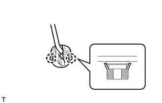
4. REMOVE SATELLITE RADIO ANTENNA ASSEMBLY (a) Disconnect the connector.  Text in Illustration Text in Illustration
(b) Detach the 3 clamps. (c) Remove the nut.
|
Toyota Tundra Service Manual > Lighting System: Door Courtesy Switch Circuit
DESCRIPTION The main body ECU (multiplex network body ECU) detects the condition of the door courtesy light switch assembly. WIRING DIAGRAM PROCEDURE 1. READ VALUE USING TECHSTREAM (a) Using the Techstream, read the Data List. Click here Main Body Tester Display Measurement Item / Range Normal Condi ...