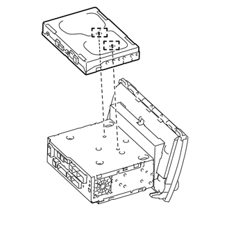
INSTALLATION PROCEDURE 1. INSTALL STEREO COMPONENT TUNER ASSEMBLY
2. INSTALL NO. 2 RADIO RECEIVER BRACKET (a) Install the No. 2 radio receiver bracket with the 5 bolts. Torque: 3.5 N·m {36 kgf·cm, 31 in·lbf} 3. INSTALL NO. 1 RADIO RECEIVER BRACKET (a) Install the No. 1 radio receiver bracket with the 5 bolts. Torque: 3.5 N·m {36 kgf·cm, 31 in·lbf} 4. INSTALL NO. 1 NAVIGATION WIRE (a) Connect each connector to install the No. 1 navigation wire. 5. INSTALL RADIO AND DISPLAY RECEIVER ASSEMBLY 6. INSTALL AIR CONDITIONING CONTROL ASSEMBLY 7. INSTALL CENTER LOWER INSTRUMENT COVER 8. CONNECT CABLE TO NEGATIVE BATTERY TERMINAL NOTICE: When disconnecting the cable, some systems need to be initialized after the cable is reconnected (See page
|
Toyota Tundra Owners Manual > Do-it-yourself maintenance: Tires
Replace or rotate tires in accordance with maintenance schedules and treadwear. Checking tires Check if the treadwear indicators are showing on the tires. Also check the tires for uneven wear, such as excessive wear on one side of the tread. Check the spare tire condition and pressure if not rotate ...