Toyota Tundra Service Manual: Inspection

INSPECTION

PROCEDURE

1. INSPECT STEERING PAD SWITCH ASSEMBLY

(a) Measure the resistance according to the value(s) in the table below.

*A

w/ Lane Departure Alert System

-

-

*1

VOLUME+

*2

VOLUME-

*3

SEEK+

*4

SEEK-

*5

VOICE

*6

MODE HOLD

*7

OFF HOOK

*8

ON HOOK

*9

UP

*10

DOWN

*11

RIGHT

*12

LEFT

*13

ENTER

*14

BACK

*15

TOP

*16

ACC

*17

LDA

-

-

*a

Component without harness connected

-

-

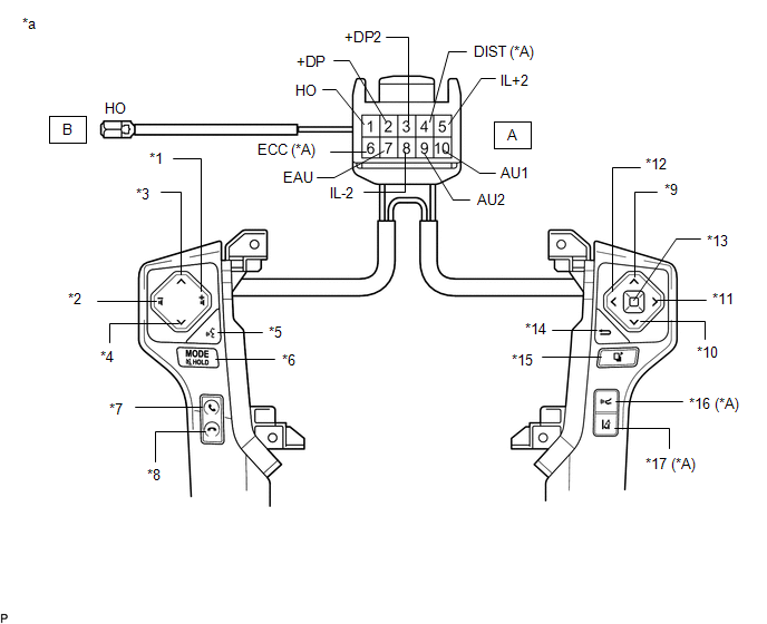
Standard Resistance:

Tester Connection

Switch Condition

Specified Condition

*:w/ Lane Departure Alert System

A2 (+DP) - A7 (EAU)

No switch is pushed

100 kΩ or higher

ENTER switch is pushed

Below 2.5 Ω

TOP switch is pushed

312 to 345 Ω

BACK switch is pushed

950 to 1050 Ω

A3 (+DP2) - A7 (EAU)

No switch is pushed

100 kΩ or higher

RIGHT switch is pushed

2954 to 3265 Ω

LEFT switch is pushed

Below 2.5 Ω

UP switch is pushed

312 to 345 Ω

DOWN switch is pushed

950 to 1050 Ω

A9 (AU2) - A7 (EAU)

No switch is pushed

100 kΩ or higher

MODE switch is pushed

Below 2.5 Ω

ON HOOK switch is pushed

312 to 345 Ω

OFF HOOK switch is pushed

950 to 1050 Ω

VOICE switch is pushed

2954 to 3265 Ω

A10 (AU1) - A7 (EAU)

No switch is pushed

100 kΩ or higher

SEEK+ switch is pushed

Below 2.5 Ω

SEEK- switch is pushed

312 to 345 Ω

VOLUME+ switch is pushed

950 to 1050 Ω

VOLUME- switch is pushed

2954 to 3265 Ω

A4 (DIST) - A6 (ECC)*

No switch is pushed

100 kΩ or higher

ACC switch is pushed

Below 2.5 Ω

LDA switch is pushed

228 to 252 Ω

B (HO) - A1 (HO)

Always

Below 2.5 Ω

If the result is not as specified, replace the steering pad switch assembly.

(b) Check the illumination.

(1) Connect the battery positive (+) lead to terminal A5 (IL+2) and the negative (-) lead to terminal A8 (IL-2) of the steering pad switch assembly connector.

(2) Check that the switch illumination comes on.

OK:

Steering pad switch illumination comes on.

If the result is not as specified, replace the steering pad switch assembly.

    Components

    Installation

    See More:

    Toyota Tundra Service Manual > Rear Door(for Double Cab): Reassembly
    REASSEMBLY CAUTION / NOTICE / HINT HINT: Use the same procedures for the RH side and LH side. The procedures listed below are for the LH side. A bolt without a torque specification is shown in the standard bolt chart (see page ). PROCEDURE 1. INSTALL REAR DOOR WEATHERSTRIP LH (a) Attach the 34 clips ...

    Toyota Tundra Owners Manual

    Toyota Tundra Service Manual

    © 2024 Copyright www.ttundra.com
    0.0356