DESCRIPTION Each unit of the navigation system connected to the AVC-LAN (communication bus) transfers the switch signals using the AVC-LAN. If a short to +B or short to ground occurs in the AVC-LAN, the navigation system will not function normally because communication is not possible. WIRING DIAGRAM 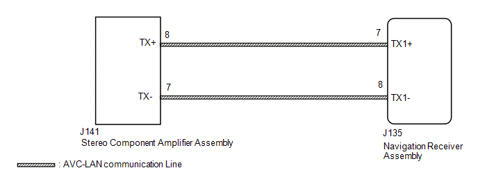 CAUTION / NOTICE / HINT HINT: The navigation receiver assembly is the master unit. PROCEDURE
 (a) for Column Shift Type: (1) Remove the navigation receiver assembly with the connector(s) still connected (See page
(b) for Floor Shift Type: (1) Remove the navigation receiver assembly with the connector(s) still connected (See page
(c) Measure the resistance according to the value(s) in the table below. Standard Resistance:
(a) Disconnect the J135 navigation receiver assembly connector. (b) Disconnect the J141 stereo component amplifier assembly connector. (c) Measure the resistance according to the value(s) in the table below. Standard Resistance:
(a) Disconnect and reconnect each slave unit one by one until the master unit returns to normal operation. HINT:
OK: Master unit returns to normal operation. Result
|
Toyota Tundra Service Manual > Tire Pressure Warning System: Dtc Check / Clear
DTC CHECK / CLEAR CHECK DTC (for TIRE PRESSURE WARNING ECU AND RECEIVER) (USING TECHSTREAM) (a) Turn the ignition switch off. (b) Connect the Techstream to the DLC3. (c) Turn the ignition switch to ON (d) Turn the Techstream on. (e) Enter the following menus: Chassis / Tire Pressure Monitor / Troubl ...

 ).
).


